Intel D845PEMY Product Guide
Intel D845PEMY Manual
 |
View all Intel D845PEMY manuals
Add to My Manuals
Save this manual to your list of manuals |
Intel D845PEMY manual content summary:
- Intel D845PEMY | Product Guide - Page 1
Intel® Desktop Board D845PEMY Product Guide Order Number: C82029-001 - Intel D845PEMY | Product Guide - Page 2
of the Intel® Desktop Board D845PEMY Product Guide Date July 2004 If an FCC declaration of conformity marking is present on the board, the following energy and, if not installed and used in accordance with the instructions, may cause harmful interference to radio communications. However, there is - Intel D845PEMY | Product Guide - Page 3
Preface This Product Guide gives information about board layout, component installation, BIOS update, and regulatory requirements for Intel® Desktop Board D845PEMY. Intended Audience The Product Guide is intended for technically qualified personnel. It is not intended for general audiences. - Intel D845PEMY | Product Guide - Page 4
Intel Desktop Board D845PEMY Product Guide Terminology The table below gives descriptions to some common terms used in the product guide. Term GB GHz KB MB Mbit MHz Description Gigabyte (1,073,741,824 bytes) Gigahertz (one billion hertz) Kilobyte (1024 bytes) Megabyte (1,048,576 bytes) Megabit - Intel D845PEMY | Product Guide - Page 5
Contents 1 Desktop Board Features Desktop Board Components 11 Processor ...13 Main Memory ...14 Intel® D845PE Chipset...15 Audio Subsystem ...15 LAN Subsystem ...16 LAN Subsystem Software 16 RJ-45 LAN Connector LEDs 16 Enhanced IDE Interface ...16 Expansion Slots ...16 BIOS...17 PCI Auto - Intel D845PEMY | Product Guide - Page 6
Intel Desktop Board D845PEMY Product Guide Connecting Hardware Control and Power Cables 35 Connecting Fans ...36 Connecting Power Cables 36 Connecting the Chassis Intrusion Cable 36 Locating the Add-in Card and Peripheral Interface Connectors 37 Setting the BIOS Configuration Jumper Block 38 - Intel D845PEMY | Product Guide - Page 7
Tables 1. Feature Summary...9 2. Desktop Board Components 12 3. Processor Support...13 4. Memory Support ...14 5. RJ-45 LAN Connector LEDs 16 6. Front Panel Audio Header Signal Names (J8A1 33 7. Front Panel Header ...34 8. USB Header ...34 9. Jumper Settings for the BIOS Setup Program Modes 38 - Intel D845PEMY | Product Guide - Page 8
Intel Desktop Board D845PEMY Product Guide viii - Intel D845PEMY | Product Guide - Page 9
the major features of Intel® Desktop Board D845PEMY. Table 1. Feature Summary Form Factor Processor Memory Chipset Audio LAN I/O Control Expansion Capabilities Peripheral Interfaces BIOS Power Management MicroATX at 9.2 inches by 8.6 inches Support for: • Intel® Pentium® 4 processor in an - Intel D845PEMY | Product Guide - Page 10
Intel Desktop Board D845PEMY Product Guide NOTE For information about this Intel desktop board, including the Technical Product Specification (TPS), BIOS updates, and device drivers, go to the Intel World Wide Web site at: http://support.intel.com/support/motherboards/desktop/ Supported Operating - Intel D845PEMY | Product Guide - Page 11
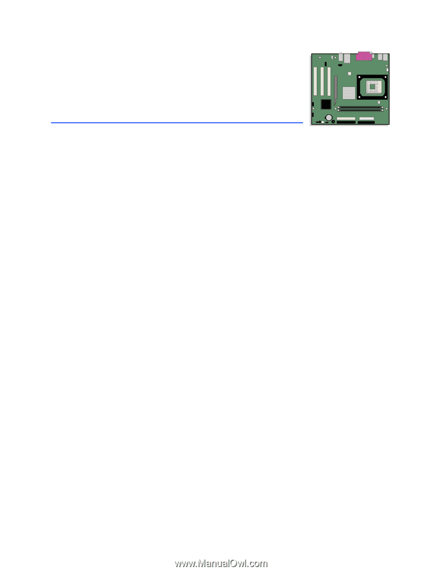
Desktop Board Features Desktop Board Components Figure 1 shows the approximate location of the major components on Desktop Board D845PEMY. Line In USB S A B R Q C D P E O N M LK J I H G F Figure 1. Desktop Board Components OM17235 11 - Intel D845PEMY | Product Guide - Page 12
header P Front panel USB header Q PCI connectors R AGP connector S Front panel audio header Related Links: Go to the following links for more information about Intel Desktop Board D845PEMY: • http://www.intel.com/design/motherbd • http://support.intel.com/support/motherboards/desktop 12 - Intel D845PEMY | Product Guide - Page 13
provide extra power to the Intel D845PE chipset and Intel processor. Related Links: Go to the following links or pages for more information about: • Supported Intel® processors for Desktop Board D845PEMY http://support.intel.com/support/motherboards/desktop/ • Instructions on installing or upgrading - Intel D845PEMY | Product Guide - Page 14
Intel Desktop Board D845PEMY Product Guide Main Memory NOTE To be fully compliant with all applicable Intel® SDRAM memory specification addendums, the desktop board should be populated with DIMMs that support the Serial Presence Detect (SPD) data structure. If your memory modules do not support - Intel D845PEMY | Product Guide - Page 15
power either headphones or amplified speakers only. Poor audio quality may occur if passive (non-amplified) speakers are connected to this output. Related Links: Go to the following link for more information about audio drivers and utilities: http://support.intel.com/support/motherboards/desktop/ 15 - Intel D845PEMY | Product Guide - Page 16
Software For LAN software and drivers, refer to the D845PEMY link on Intel's World Wide Web site at: http://support.intel.com/support/motherboards/desktop/ RJ-45 LAN Connector LEDs Two LEDs are built into the RJ-45 LAN connector. Table 5 describes the LED states when the desktop board is powered - Intel D845PEMY | Product Guide - Page 17
Desktop Board Features BIOS The BIOS provides the Power-On Self-Test (POST), the BIOS Setup program, the PCI and IDE auto-configuration utilities, and the video BIOS. The BIOS is stored in the firmware hub. The BIOS can be updated by following the instructions in Chapter 3 on page 45. PCI Auto - Intel D845PEMY | Product Guide - Page 18
Intel Desktop Board D845PEMY Product Guide Chassis Intrusion The board supports a chassis security feature that detects if the chassis cover has been removed. The security feature uses a mechanical switch on the chassis that can be connected to the chassis intrusion header on the desktop board. See - Intel D845PEMY | Product Guide - Page 19
. Related Links: For more information on standby current requirements, navigate to the TPS by first selecting the desktop board name from the following link: http://support.intel.com/support/motherboards/desktop/ Wake from USB USB bus activity wakes the computer from an ACPI S1 or S3 state. NOTE - Intel D845PEMY | Product Guide - Page 20
Intel Desktop Board D845PEMY Product Guide 20 - Intel D845PEMY | Product Guide - Page 21
Components This chapter tells you how to: • Install the I/O shield • Install and remove the desktop board • Install and remove a processor • Install a AGP video adapter card • Install and remove memory • Connect the IDE cable • Connect internal headers • Connect fans and power cables • Locate the - Intel D845PEMY | Product Guide - Page 22
Intel Desktop Board D845PEMY Product Guide Follow these guidelines before you begin: • Always instruct you to refer computer servicing to qualified technical personnel. Installation Instructions CAUTION Follow these guidelines to meet safety and regulatory requirements when installing this board - Intel D845PEMY | Product Guide - Page 23
The Industry Canada statement at the front of this product guide demonstrates compliance with Canadian EMC regulations. Industry Canada recognizes . Place Battery Marking There is insufficient space on this Desktop Board to provide instructions for replacing and disposing of the Lithium ion coin cell - Intel D845PEMY | Product Guide - Page 24
Intel Desktop Board D845PEMY Product Guide Related Links: For information about replacing the battery, go to page 41 in Chapter 2. Use Only for Intended Applications All Intel desktop boards are evaluated as Information Technology Equipment (I.T.E.) for use in personal computers for installation in - Intel D845PEMY | Product Guide - Page 25
the computer can result in personal injury or equipment damage. Refer to your chassis manual for instructions on installing and removing the desktop board. Figure 3 shows the location of the six mounting holes for Desktop Board D845PEMY. Figure 3. Desktop Board Mounting Screw Holes OM17237 25 - Intel D845PEMY | Product Guide - Page 26
Intel Desktop Board D845PEMY Product Guide Installing and Removing a Processor Instructions on how to install the processor to the desktop board are given below. Installing a Processor CAUTION Before installing or removing the processor, make sure that AC power has been removed by unplugging the - Intel D845PEMY | Product Guide - Page 27
and Replacing Desktop Board Components Connecting the Processor Fan Heatsink Cable Connect the processor fan heatsink cable to the processor fan header (see Figure 5). OM17275 Figure 5. Connecting the Processor Fan Heatsink Cable to the Processor Fan Header Removing a Processor For instruction on - Intel D845PEMY | Product Guide - Page 28
Intel Desktop Board D845PEMY Product Guide Installing and Removing an AGP Card CAUTION When installing any AGP card in the desktop board, supports 0.8 V (4x and 1x) AGP cards. The desktop board has an integrated AGP card retention mechanism (RM). Installing an AGP Card Follow these instructions - Intel D845PEMY | Product Guide - Page 29
with all applicable Intel SDRAM memory specification addendums, the board requires DIMMs that support the Serial Presence Detect (SPD) data structure. You can access the PC Serial Presence Detect Specification at: http://www.intel.com/technology/memory/pcsdram/spec/ The desktop board has two DIMM - Intel D845PEMY | Product Guide - Page 30
Intel Desktop Board D845PEMY Product Guide 4. Make sure the clips at either end of the DIMM socket(s) cord. Connecting the IDE Cable The Intel® boxed desktop board package includes an IDE cable. The cable connects two drives to the desktop board. The cable supports both ATA-66 and ATA-100 transfer - Intel D845PEMY | Product Guide - Page 31
the cable: 1. Observe the precautions in "Before You Begin" on page 21. 2. Attach the cable end with the single blue connector to the desktop board (see Figure 8, A). 3. Attach the cable end with the two closely spaced black and gray connectors to the drives (see Figure 8, B). Figure 8. Connecting - Intel D845PEMY | Product Guide - Page 32
Intel Desktop Board D845PEMY Product Guide Connecting Internal Headers Follow the instructions below to connect the USB, power LED, and front panel solutions. See Figure 9 for pin assignments. A 1 2 3 4 5 6 7 9 10 D 1 2 3 4 5 6 7 8 10 B 1 2 3 4 5 6 7 8 9 13 C Item - Intel D845PEMY | Product Guide - Page 33
Installing and Replacing Desktop Board Components Installing a Front Panel Audio Solution Table 6 shows the pin assignments for the front panel audio header. Table 6. Front Panel Audio Header Signal Names (J8A1) Pin Signal Name Pin Signal Name 1 AUD-MIC 3 AUD-MIC-BIAS 2 AUD-GND 4 AUD- - Intel D845PEMY | Product Guide - Page 34
Intel Desktop Board D845PEMY Product Guide Connecting the Front Panel Header Before connecting the front panel header, observe the precautions in "Before You Begin" on page 21. Table 7 shows the pin - Intel D845PEMY | Product Guide - Page 35
Installing and Replacing Desktop Board Components Connecting Hardware Control and Power Cables Figure 10 shows the location of the chassis intrusion header, fan headers, and power connectors. A 1 2 B C E 1 D 2 1 Item A B C D E Description 12 V - Intel D845PEMY | Product Guide - Page 36
Intel Desktop Board D845PEMY Product Guide Connecting Fans See Figure 10 for fan header locations. Connect the processor's fan heatsink cable to the processor fan header on the board. Connect the chassis fan cable to the board fan header. Connecting Power Cables CAUTION Failure to use an ATX12V - Intel D845PEMY | Product Guide - Page 37
Installing and Replacing Desktop Board Components Locating the Add-in Card and Peripheral Interface Connectors Figure 11 shows the location of the PCI bus add-in card, AGP, diskette drive, - Intel D845PEMY | Product Guide - Page 38
Intel Desktop Board D845PEMY Product Guide Setting the BIOS Configuration Jumper Block Figure 12 shows the location of the BIOS configuration jumper block. 31 J9H2 OM17243 Figure 12. Location of the BIOS Configuration Jumper Block The three-pin BIOS jumper block enables all board configurations - Intel D845PEMY | Product Guide - Page 39
Installing and Replacing Desktop Board Components Clearing Passwords This procedure assumes that the board is installed in the computer and the configuration jumper block is set to normal mode. 1. Observe the precautions in "Before You Begin" on page 21. 2. - Intel D845PEMY | Product Guide - Page 40
Intel Desktop Board D845PEMY Product Guide Back Panel Connectors NOTE The line out connector, located on the back panel, is designed to power either headphones or amplified speakers only. Poor audio quality may occur if passive (non-amplified) speakers are connected to this output. Figure 13 shows - Intel D845PEMY | Product Guide - Page 41
Installing and Replacing Desktop Board Components Replacing the Battery A coin-cell battery (CR2032 ºC with 3.3 VSB applied. When the voltage drops below a certain level, the BIOS Setup program settings stored in CMOS RAM (for example, the date and time) might not be accurate. Replace the battery - Intel D845PEMY | Product Guide - Page 42
Intel Desktop Board D845PEMY Product Guide PRECAUCIÓN Existe peligro de explosión si la pila no se cambia de forma adecuada. Utilice solamente pilas iguales o del mismo tipo que las recomendadas por - Intel D845PEMY | Product Guide - Page 43
Installing and Replacing Desktop Board Components AWAS Risiko letupan wujud jika bateri digantikan dengan jenis yang tidak betul. Bateri sepatutnya dikitar semula jika boleh. Pelupusan bateri terpakai mestilah mematuhi peraturan - Intel D845PEMY | Product Guide - Page 44
Intel Desktop Board D845PEMY Product Guide To replace the battery, follow these steps: 1. Observe the precautions in "Before You Begin" on page 21. 2. the connector, orienting the "+" and "-" correctly. 8. Replace the computer cover. OM17245 Figure 14. Removing the Battery from the Desktop Board 44 - Intel D845PEMY | Product Guide - Page 45
. To update the BIOS with the Intel Express BIOS Update utility: 1. Go to the Intel World Wide Web site: http://support.intel.com/support/motherboards/desktop/ 2. Navigate to the D845PEMY page, click "[view] Latest BIOS updates", and select the Express BIOS Update utility file. 3. Download the file - Intel D845PEMY | Product Guide - Page 46
://support.intel.com/support/motherboards/desktop/ Navigate to the D845PEMY page, click "[view] Latest BIOS updates", and select the Intel Iflash BIOS Update utility file. NOTE Review the instructions distributed with the update utility before attempting a BIOS update. The Intel Iflash BIOS update - Intel D845PEMY | Product Guide - Page 47
jumper block (see Figure 12). 3. Remove the jumper from all pins as shown below to set recovery mode for Setup. 31 4. Insert the bootable BIOS update diskette into diskette drive A. 5. Replace the computer cover, connect the power cord, turn on the computer, and allow it to boot. The recovery - Intel D845PEMY | Product Guide - Page 48
Intel Desktop Board D845PEMY Product Guide 48 - Intel D845PEMY | Product Guide - Page 49
4 Desktop Board Resources Memory Map Table 10. System Memory Map Address Range (decimal) Address Range (hex) KB 512 KB Description Extended Memory Runtime BIOS Reserved Available high DOS memory (open to the PCI bus) Video memory and BIOS Extended BIOS data (movable by memory manager software - Intel D845PEMY | Product Guide - Page 50
Intel Desktop Board D845PEMY Product Guide Interrupts Table 12. Interrupts IRQ System Resource NMI I/O channel check 0 Reserved, interval timer 1 Reserved, keyboard buffer full 2 Reserved, cascade interrupt from slave PIC 3 COM2* 4 COM1* 5 - Intel D845PEMY | Product Guide - Page 51
Desktop Board D845PEMY reports POST errors in two ways: • By sounding a beep code • By displaying an error message on the monitor BIOS Beep Codes The BIOS beep codes are listed in Table 13. The BIOS also issues a beep code (one long tone followed by two short tones) during POST if the video - Intel D845PEMY | Product Guide - Page 52
Intel Desktop Board D845PEMY Product Guide BIOS Error Messages When a recoverable error occurs during the POST, the BIOS displays an error message describing the problem. Table 14. BIOS Error Messages Error Message Explanation GA20 Error An error occurred with Gate-A20 when switching to - Intel D845PEMY | Product Guide - Page 53
Error Messages and Indicators Table 14. BIOS Error Messages (continued) Error Message Memory Size Decreased Memory Size Increased Memory Size Changed No Boot Device Available Off Board Parity Error On Board Parity Error Parity Error NVRAM / CMOS / PASSWORD cleared by Jumper Pressed - Intel D845PEMY | Product Guide - Page 54
Intel Desktop Board D845PEMY Product Guide 54 - Intel D845PEMY | Product Guide - Page 55
- Safety - Part 1: General Requirements (International) European Union Declaration of Conformity Statement We, Intel Corporation, declare under our sole responsibility that the product Intel® Desktop Board D845PEMY is in conformity with all applicable essential requirements necessary for CE marking - Intel D845PEMY | Product Guide - Page 56
Intel Desktop Board D845PEMY Product Guide Dansk Dette produkt er i overensstemmelse med det europæiske direktiv 89/336/EEC & 73/23/EEC. Dutch Dit product is in navolging van de bepalingen - Intel D845PEMY | Product Guide - Page 57
Regulatory Compliance EMC Regulations Desktop Board D845PEMY complies with the EMC regulations stated in Table 16 it may cause radio interference. Install and use the equipment according to the instruction manual. Korean Class B statement translated as follows: This is household equipment that is - Intel D845PEMY | Product Guide - Page 58
Intel Desktop Board D845PEMY Product Guide Product Certification Markings (Board Level) Desktop Board D845PEMY has the following product certification markings: Table 17. Product Certification Markings Description UL joint US/Canada Recognized Component mark. Includes adjacent UL file number for
-
 1
1 -
 2
2 -
 3
3 -
 4
4 -
 5
5 -
 6
6 -
 7
7 -
8
-
9
-
10
-
11
-
12
-
13
-
14
-
15
-
16
-
17
-
18
-
19
-
20
-
21
-
22
-
23
-
24
-
25
-
26
-
27
-
28
-
29
-
30
-
31
-
32
-
33
-
34
-
35
-
36
-
37
-
38
-
39
-
40
-
41
-
42
-
43
-
44
-
45
-
46
-
47
-
48
-
49
-
50
-
51
-
52
-
53
-
54
-
55
-
56
-
57
-
58
 |
 |
Intel
®
Desktop Board
D845PEMY Product Guide
Order Number:
C8202
9
-001