Intel D915GAV User Manual - Page 7

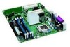
Location of the PCI Bus and PCI Express Add-in Card, and Peripheral Interface - desktop board

Page 7 highlights

Contents 5 Desktop Board Resources Memory Map ...71 DMA Channels ...71 Interrupts ...72 A Error Messages and Indicators BIOS Beep Codes...73 BIOS Error Messages ...74 B Regulatory Compliance Safety Regulations ...77 European Union Declaration of Conformity Statement 77 Product Ecology Statements 78 EMC Regulations ...79 Product Certification Markings (Board Level 80 Figures 1. Desktop Boards D915GAV and D915GEV Components 12 2. Intel Desktop Boards D915GUX and D915GAG Components 14 3. Back Panel LAN Connector LED Locations 20 4. Location of Standby Power Indicator 25 5. Installing the I/O Shield 30 6. Desktop Boards D915GEV and D915GAV Mounting Screw Hole Locations 31 7. Lift Socket Lever...32 8. Lift the Load Plate and Don't Touch the Socket Contacts 32 9. Remove the Protective Socket Cover 33 10. Remove the Processor from the Protective Processor Cover/Do Not Touch 33 11. Install Processor ...34 12. Close the Load Plate ...34 13. Connecting the Processor Fan Heat Sink Cable to the Processor Fan Connector ........ 35 14. Dual Configuration Example 1 36 15. Dual Configuration Example 2 37 16. Dual Configuration Example 3 37 17. Matching the Correct DIMM 38 18. Installing a DIMM...39 19. Inserting the PCI Express x16 Card and Covering the Back Panel VGA Port 41 20. Connecting the IDE Cable 42 21. Connecting the Serial ATA Cable 43 22. Internal Headers ...44 23. Back Panel Audio Connectors for Flexible 6-Channel Audio System 47 24. Location of Fan Headers 48 25. Connecting 2x10 Power Supply Cables 49 26. Connecting 2x12 Power Supply Cables 50 27. Location of the PCI Bus and PCI Express Add-in Card, and Peripheral Interface Connectors for Desktop Boards D915GAV and D915GEV 51 28. Location of the BIOS Configuration Jumper Block 52 29. Back Panel Connectors 54 30. Removing the Battery ...58 vii

  • 1
  • 2
  • 3
  • 4
  • 5
  • 6
  • 7
  • 8
  • 9
  • 10
  • 11
  • 12
  • 13
  • 14
  • 15
  • 16
  • 17
  • 18
  • 19
  • 20
  • 21
  • 22
  • 23
  • 24
  • 25
  • 26
  • 27
  • 28
  • 29
  • 30
  • 31
  • 32
  • 33
  • 34
  • 35
  • 36
  • 37
  • 38
  • 39
  • 40
  • 41
  • 42
  • 43
  • 44
  • 45
  • 46
  • 47
  • 48
  • 49
  • 50
  • 51
  • 52
  • 53
  • 54
  • 55
  • 56
  • 57
  • 58
  • 59
  • 60
  • 61
  • 62
  • 63
  • 64
  • 65
  • 66
  • 67
  • 68
  • 69
  • 70
  • 71
  • 72
  • 73
  • 74
  • 75
  • 76
  • 77
  • 78
  • 79
  • 80

Contents
vii
5
Desktop Board Resources
Memory Map
.........................................................................................................................
71
DMA Channels
......................................................................................................................
71
Interrupts
...............................................................................................................................
72
A
Error Messages and Indicators
BIOS Beep Codes
.................................................................................................................
73
BIOS Error Messages
...........................................................................................................
74
B
Regulatory Compliance
Safety Regulations
................................................................................................................
77
European Union Declaration of Conformity Statement
.........................................................
77
Product Ecology Statements
.................................................................................................
78
EMC Regulations
..................................................................................................................
79
Product Certification Markings (Board Level)
........................................................................
80
Figures
1.
Desktop Boards D915GAV and D915GEV Components
...............................................
12
2.
Intel Desktop Boards D915GUX and D915GAG Components
.......................................
14
3.
Back Panel LAN Connector LED Locations
...................................................................
20
4.
Location of Standby Power Indicator
..............................................................................
25
5.
Installing the I/O Shield
...................................................................................................
30
6.
Desktop Boards D915GEV and D915GAV Mounting Screw Hole Locations
.................
31
7.
Lift Socket Lever
.............................................................................................................
32
8.
Lift the Load Plate and Don’t Touch the Socket Contacts
..............................................
32
9.
Remove the Protective Socket Cover
.............................................................................
33
10. Remove the Processor from the Protective Processor Cover/Do Not Touch
.................
33
11. Install Processor
.............................................................................................................
34
12. Close the Load Plate
......................................................................................................
34
13. Connecting the Processor Fan Heat Sink Cable to the Processor Fan Connector
........
35
14. Dual Configuration Example 1
........................................................................................
36
15. Dual Configuration Example 2
........................................................................................
37
16. Dual Configuration Example 3
........................................................................................
37
17. Matching the Correct DIMM
............................................................................................
38
18. Installing a DIMM
............................................................................................................
39
19. Inserting the PCI Express x16 Card and Covering the Back Panel VGA Port
...............
41
20. Connecting the IDE Cable
..............................................................................................
42
21. Connecting the Serial ATA Cable
...................................................................................
43
22. Internal Headers
.............................................................................................................
44
23. Back Panel Audio Connectors for Flexible 6-Channel Audio System
............................
47
24. Location of Fan Headers
................................................................................................
48
25. Connecting 2x10 Power Supply Cables
.........................................................................
49
26. Connecting 2x12 Power Supply Cables
.........................................................................
50
27. Location of the PCI Bus and PCI Express Add-in Card, and Peripheral Interface
Connectors for Desktop Boards D915GAV and D915GEV
............................................
51
28. Location of the BIOS Configuration Jumper Block
.........................................................
52
29. Back Panel Connectors
..................................................................................................
54
30. Removing the Battery
.....................................................................................................
58