Intel D915GLVG D915GLVG Technical Product Specification
Intel D915GLVG Manual
 |
View all Intel D915GLVG manuals
Add to My Manuals
Save this manual to your list of manuals |
Intel D915GLVG manual content summary:
- Intel D915GLVG | D915GLVG Technical Product Specification - Page 1
April 2005 Order Number: D18285-001US The Intel® Desktop Board D915GLVG may contain design defects or errors known as errata that may cause the product to deviate from published specifications. Current characterized errata are documented in the Intel Desktop Board D915GLVG Specification Update. - Intel D915GLVG | D915GLVG Technical Product Specification - Page 2
Intel Desktop Board D915GLVG with BIOS identifier VG91510A.86A. Changes to this specification will be published in the Intel Desktop Board D915GLVG Specification Update before being incorporated into a revision of this document. INFORMATION IN THIS DOCUMENT IS PROVIDED IN CONNECTION WITH INTEL - Intel D915GLVG | D915GLVG Technical Product Specification - Page 3
Preface This Technical Product Specification (TPS) specifies the board layout, components, connectors, power and environmental requirements, and the BIOS for the Intel® Desktop Board D915GLVG. It describes the standard product and available manufacturing options. Intended Audience The TPS is - Intel D915GLVG | D915GLVG Technical Product Specification - Page 4
Intel Desktop Board D915GLVG Technical Product Specification Other Common Notation # (NxnX) GB GB/sec of a component, N indicates component type, xn are the relative coordinates of its location on the board, and X is the instance of the particular part at that general location. For example, J5J1 - Intel D915GLVG | D915GLVG Technical Product Specification - Page 5
1.1.1 Feature Summary 10 1.1.2 Board Layout 12 1.1.3 Block Diagram 14 1.2 Online Support ...15 1.3 Processor ...15 1.4 System Memory ...16 1.4.1 Memory Configurations 18 1.5 Intel® 915GL Chipset 22 1.5.1 Intel® GMA900 Graphics Controller 22 1.5.2 USB ...23 1.5.3 IDE Support 24 1.5.4 Real-Time - Intel D915GLVG | D915GLVG Technical Product Specification - Page 6
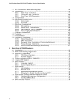
Intel Desktop Board D915GLVG Technical Product Specification 2.7 PCI Conventional Interrupt Routing Map 45 2.8 Connectors...46 2.8.1 Back Panel Connectors 47 2.8.2 Component-side Connectors 48 2.8.3 Front Panel USB Connectors 54 2.9 Jumper Block ...55 2.10 Mechanical Considerations 56 2.10.1 - Intel D915GLVG | D915GLVG Technical Product Specification - Page 7
47 16. Component-side Connectors 48 17. Connection Diagram for Front Panel Connector 53 18. Connection Diagram for Front Panel USB Connectors 54 19. Location of the Jumper Block 55 20. Board Dimensions...56 21. I/O Shield Dimensions 57 22. Processor Heatsink for Omni-directional Airflow 60 23 - Intel D915GLVG | D915GLVG Technical Product Specification - Page 8
Intel Desktop Board D915GLVG Technical Product Specification 15. Back Panel Connectors Shown in Figure 15 47 16. Component-side Connectors Shown in Figure 16 49 17. Front Panel Audio Connector 49 18. Chassis Intrusion Connector 50 19. Serial ATA Connectors 50 20. Processor Fan Connector 50 21. - Intel D915GLVG | D915GLVG Technical Product Specification - Page 9
What This Chapter Contains 1.1 Overview ...10 1.2 Online Support ...15 1.3 Processor ...15 1.4 System Memory ...16 1.5 Intel® 915GL Chipset 22 1.6 PCI Express Connectors 25 1.7 I/O Controller...26 1.8 Audio Subsystem ...27 1.9 LAN Subsystem ...29 1.10 Hardware Management Subsystem 30 1.11 - Intel D915GLVG | D915GLVG Technical Product Specification - Page 10
82915GL Graphics Memory Controller Hub (GMCH) • Intel® 82801FB I/O Controller Hub (ICH6) • 4 Mbit Firmware Hub (FWH) Intel® GMA900 onboard graphics subsystem Intel® High Definition Audio subsystem using the Realtek ALC860 audio codec LPC Bus I/O controller USB Peripheral Interfaces LAN Support BIOS - Intel D915GLVG | D915GLVG Technical Product Specification - Page 11
Available PC Technology • Support for PCI Local Bus Specification Revision 2.2 • Support for PCI Express Revision 1.0a • Suspend to RAM support • Wake on PCI, RS-232, front panel, PS/2 devices, and USB ports Hardware Monitor Subsystem • Hardware monitoring and fan control ASIC • Voltage sense - Intel D915GLVG | D915GLVG Technical Product Specification - Page 12
Intel Desktop Board D915GLVG Technical Product Specification 1.1.2 Board Layout Figure 1 shows the location of the major components. A B CD E F G CC BB H I AA J K L Z M X VT Y W U SR Q P ON Figure 1. Board Components Table 2 lists the components identified in Figure 1. OM17803 12 - Intel D915GLVG | D915GLVG Technical Product Specification - Page 13
ALC860 audio codec B Front panel audio connector C PCI Conventional bus add-in card connectors D Ethernet PLC device E Rear chassis fan connector F Back panel connectors G +12V power connector (ATX12V) H LGA775 processor socket I Hardware monitoring and fan control ASIC J Processor - Intel D915GLVG | D915GLVG Technical Product Specification - Page 14
) USB Back Panel/ Front Panel USB Ports LPC Bus I/O Controller LPC Bus Serial Port Parallel Port PS/2 Mouse PS/2 Keyboard Diskette Drive Connector DMI Interconnect High Definition Audio Link LAN Connect Interface Intel 82915GL Graphics and Memory Controller Hub (GMCH) VGA Port Channel A DIMMs - Intel D915GLVG | D915GLVG Technical Product Specification - Page 15
find information about... Intel Desktop Board D915GLVG under "Desktop Board Products" or "Desktop Board Support" Available configurations for the Desktop Board D915GLVG Processor data sheets ICH6 addressing Custom splash screens Audio software and utilities LAN software and drivers Visit this World - Intel D915GLVG | D915GLVG Technical Product Specification - Page 16
Intel Desktop Board D915GLVG Technical Product Specification 1.4 System Memory The boards have four DIMM sockets and support the following memory features: • 2.5 V (only) DDR SDRAM DIMMs with gold-plated contacts • Unbuffered, single-sided or double-sided DIMMs with the following restriction: - Intel D915GLVG | D915GLVG Technical Product Specification - Page 17
Product Description Table 4 lists the supported DIMM configurations. Table 4. Supported Memory Configurations DIMM Capacity SDRAM Configuration Density SDRAM Organization Front-side/Back-side Number of SDRAM Devices 128 MB SS 256 Mbit 16 M x 16/empty 4 256 MB SS 256 Mbit 32 M x 8/ - Intel D915GLVG | D915GLVG Technical Product Specification - Page 18
Desktop Board D915GLVG Technical Product Specification 1.4.1 Memory Configurations The Intel 82915GL GMCH supports two types of memory organization: • Dual channel (Interleaved) mode. This mode offers the highest throughput for real world applications. Dual channel mode is enabled when the installed - Intel D915GLVG | D915GLVG Technical Product Specification - Page 19
Product Description 1.4.1.1 Dual Channel (Interleaved) Mode Configurations Figure 4 shows a dual channel configuration using two DIMMs. In this example, the DIMM0 (blue) sockets of both channels are populated with identical DIMMs. 1 GB 1 GB Channel A, DIMM 0 Channel A, DIMM 1 Channel B, DIMM 0 - Intel D915GLVG | D915GLVG Technical Product Specification - Page 20
Intel Desktop Board D915GLVG Technical Product Specification Figure 6 shows a dual channel configuration using four DIMMs. In this example, the combined capacity of the two DIMMs in Channel A equal the combined capacity of - Intel D915GLVG | D915GLVG Technical Product Specification - Page 21
Product Description 1.4.1.2 Single Channel (Asymmetric) Mode Configurations NOTE Dual channel (Interleaved) mode configurations provide the highest memory throughput. Figure 7 shows a single channel configuration using one DIMM. In this example, only the DIMM0 (blue) socket of Channel A is - Intel D915GLVG | D915GLVG Technical Product Specification - Page 22
Intel Desktop Board D915GLVG Technical Product Specification 1.5 Intel® 915GL Chipset The Intel 915GL chipset consists of the following devices: • Intel 82915GL Graphics Memory Controller Hub (GMCH) with Direct Media Interface (DMI) interconnect • Intel 82801FB I/O Controller Hub (ICH6) with DMI - Intel D915GLVG | D915GLVG Technical Product Specification - Page 23
of DVMT requires operating system driver support. 1.5.1.2 Configuration Modes A list of supported modes for the Intel GMA900 graphics controller is available as a downloadable document. For information about Supported modes for the D915GLVG board Refer to http://www.intel.com/design/motherbd/vg - Intel D915GLVG | D915GLVG Technical Product Specification - Page 24
Intel Desktop Board D915GLVG Technical Product Specification 1.5.3 IDE Support The boards provides five IDE interface connectors: • One parallel ATA IDE connector that supports two devices • Four serial ATA IDE connectors that support one device per connector 1.5.3.1 Parallel ATE IDE Interface The - Intel D915GLVG | D915GLVG Technical Product Specification - Page 25
Windows* XP and Windows the real-time clock and CMOS memory. When the computer is not RAM at power-on. 1.6 PCI Express* Connectors The boards provides one PCI Express x1 connector. The x1 interface supports simultaneous transfer speeds up to 500 MBytes/sec. The PCI Express interface supports the PCI - Intel D915GLVG | D915GLVG Technical Product Specification - Page 26
Intel Desktop Board D915GLVG Technical Product Specification 1.7 I/O Controller The I/O controller provides the following features: • One serial port • One parallel port with Extended Capabilities Port (ECP) and Enhanced Parallel Port (EPP) support • Serial IRQ interface compatible with serialized - Intel D915GLVG | D915GLVG Technical Product Specification - Page 27
Subsystem The boards support the Intel High Definition audio subsystem based on the Realtek ALC860 codec. The audio subsystem supports the following features: • Advanced jack sense (front and rear panel) that enables the audio codec to recognize the device that is connected to an audio port. All - Intel D915GLVG | D915GLVG Technical Product Specification - Page 28
Intel Desktop Board D915GLVG Technical Product Specification 1.8.3 Intel® High Definition Audio Subsystem The Intel High Definition Audio subsystem includes the following: • Intel 82801FB I/O Controller Hub (ICH6) • Realtek ALC860 audio codec • Microphone input that supports a single dynamic, - Intel D915GLVG | D915GLVG Technical Product Specification - Page 29
layer interface device Intel® 82562GZ PLC for 10/100 Mbits/sec Ethernet LAN connectivity. • RJ-45 LAN connector with integrated status LEDs Additional features of the LAN subsystem include: • CSMA/CD protocol engine • LAN connect interface that supports the 82562GZ • PCI Conventional bus power - Intel D915GLVG | D915GLVG Technical Product Specification - Page 30
Intel Desktop Board D915GLVG Technical Product Specification Table 5 describes the LED states when the board is powered up and the 10/100 Mbits/sec LAN subsystem is operating. Table 5. LAN Connector LED States LED Color Green Yellow LED State Off On Blinking Off On Condition LAN link is not - Intel D915GLVG | D915GLVG Technical Product Specification - Page 31
E F F E OM17806 Description Remote ambient temperature sensor Thermal diode, located on processor die Ambient temperature sensor, internal to hardware monitoring and fan control ASIC Processor fan Rear chassis fan Front chassis fan Figure 12. Location of Thermal Sensors and Fan Connectors 31 - Intel D915GLVG | D915GLVG Technical Product Specification - Page 32
Intel Desktop Board D915GLVG Technical Product Specification 1.10.3 Fan Monitoring Fan monitoring can be implemented using Intel® Desktop Utilities, LANDesk* software, or thirdparty software. The level of monitoring and control is dependent on the hardware monitoring ASIC used with the Desktop - Intel D915GLVG | D915GLVG Technical Product Specification - Page 33
Product Description Table 6 lists the system states based on how long the power switch is pressed, depending on how ACPI is configured with an ACPI-aware operating system. Table 6. Effects of Pressing the Power Switch If the system is in this state... Off (ACPI G2/G5 - Soft off) On (ACPI G0 - - Intel D915GLVG | D915GLVG Technical Product Specification - Page 34
Intel Desktop Board D915GLVG Technical Product Specification 1.11.1.1 System States and Power States Under ACPI, the operating system directs all system and device power state transitions. The operating system puts devices in and out of low-power states based on user preferences and knowledge of - Intel D915GLVG | D915GLVG Technical Product Specification - Page 35
total amount of standby current required depends on the wake devices supported and manufacturing options. The boards provide several power management hardware features, including: • Power connector • Fan connectors • LAN wake capabilities • Instantly Available PC technology • Resume on Ring • Wake - Intel D915GLVG | D915GLVG Technical Product Specification - Page 36
Intel Desktop Board D915GLVG Technical Product Specification NOTE The use of Resume on Ring and Wake from USB technologies from an ACPI state requires an operating system that provides full ACPI support. 1.11.2.1 Power Connector ATX12V-compliant power supplies can turn off the system power through - Intel D915GLVG | D915GLVG Technical Product Specification - Page 37
the front panel LED is amber if dual colored, or off if single colored.) When signaled by a wake-up device or event, the system quickly returns to its last known wake state. Table 8 on page 35 lists the devices and events that can wake the computer from the S3 state. The boards support the PCI Bus - Intel D915GLVG | D915GLVG Technical Product Specification - Page 38
Intel Desktop Board D915GLVG Technical Product Specification 1.11.2.10 +5 V Standby Power Indicator LED The +5 disconnect the power cord before installing or removing any devices connected to the board. Failure to do so could damage the board and any attached devices. CR3J1 OM17807 Figure 13. - Intel D915GLVG | D915GLVG Technical Product Specification - Page 39
with their respective section headings. 2.2 Memory Resources 2.2.1 Addressable Memory The board utilizes 4 GB of addressable system memory. Typically the address space that is allocated for PCI Conventional bus add-in cards, PCI Express configuration space, BIOS (firmware hub), and chipset overhead - Intel D915GLVG | D915GLVG Technical Product Specification - Page 40
Intel Desktop Board D915GLVG Technical Product Specification • MCH base address registers, internal graphics ranges, PCI Express ports (up to 512 MB) • Memory-mapped I/O that is dynamically allocated for PCI Conventional and PCI Express add- in cards The amount of installed memory that can be used - Intel D915GLVG | D915GLVG Technical Product Specification - Page 41
Description Extended memory Runtime BIOS Reserved Potential available high DOS memory (open to the PCI Conventional bus). Dependent on video adapter used. Video memory and BIOS Extended BIOS data (movable by memory manager software) Extended conventional memory Conventional memory 2.3 DMA Channels - Intel D915GLVG | D915GLVG Technical Product Specification - Page 42
Intel Desktop Board D915GLVG Technical Product Specification 2.4 Fixed I/O Map Table 11. I/O Map Address (hex) Size Description 0000 - 00FF 0170 - 0177 01F0 - 01F7 256 bytes 8 bytes 8 bytes Used by the Desktop Board D915GLVG. Refer to the ICH6 data sheet for dynamic addressing information. - Intel D915GLVG | D915GLVG Technical Product Specification - Page 43
02 03 00 00 00 Description Memory controller of Intel 82915GL component Integrated graphics controller Integrated graphics controller Intel High Definition Audio Controller PCI Express port 1 (PCI Express x1 bus connector) PCI Express port 2 PCI Express port 3 PCI Express port 4 (not used) USB UHCI - Intel D915GLVG | D915GLVG Technical Product Specification - Page 44
Intel Desktop Board D915GLVG Technical Product Specification 2.6 Interrupts The interrupts can be routed through either the Programmable Interrupt Controller (PIC) or the Advanced Programmable Interrupt Controller (APIC) portion of the ICH6 component. The PIC is supported in Windows 98 SE and - Intel D915GLVG | D915GLVG Technical Product Specification - Page 45
to PIRQB, which is already connected to the ICH6 audio controller. The add-in card in PCI Conventional bus connector 3 now shares an interrupt with the onboard interrupt source. Table 14. PCI Interrupt Routing Map PCI Interrupt Source ICH6 LAN PCI bus connector 1 PCI bus connector 2 PIRQA PIRQB - Intel D915GLVG | D915GLVG Technical Product Specification - Page 46
Intel Desktop Board D915GLVG Technical Product Specification 2.8 Connectors CAUTION Only the following connectors have overcurrent protection: back panel USB, front panel USB, and PS/2. The other internal connectors are not overcurrent protected and should connect only to devices inside the computer - Intel D915GLVG | D915GLVG Technical Product Specification - Page 47
port (Burgundy) D Serial port A (Teal) E VGA port F Audio line in/Retasking Port C (Light blue) G Audio line out/Retasking Port D (Lime Green) H Mic in/Retasking Port B (Pink) I USB ports (two) J LAN K USB ports (two) NOTE The back panel audio line out connector is designed to power - Intel D915GLVG | D915GLVG Technical Product Specification - Page 48
Intel Desktop Board D915GLVG Technical Product Specification 2.8.2 Component-side Connectors Figure 16 shows the locations of the component-side connectors. AB C D E 12 9 10 T 4 3 1 13 12 10 11 9 2 1 1 1 11 3 12 S 10 R Q 1 2 1 PN L J OM K - Intel D915GLVG | D915GLVG Technical Product Specification - Page 49
16 Item/callout from Figure 16 Description A Front panel audio connector B PCI Conventional bus add-in card connector 2 C PCI Conventional bus add-in card connector 1 D Rear chassis fan connector E +12V power connector (ATX12V) F Processor fan connector G Power connector H Diskette - Intel D915GLVG | D915GLVG Technical Product Specification - Page 50
Intel Desktop Board D915GLVG Technical Product Specification Table 18. Chassis Intrusion Connector Pin Signal Name 1 Intruder 2 Ground Table 19. Serial ATA Connectors Pin Signal Name 1 Ground 2 TXP 3 TXN 4 Ground 5 RXN 6 RXP 7 Ground Table 20. Processor Fan Connector Pin - Intel D915GLVG | D915GLVG Technical Product Specification - Page 51
x 10 connectors previously used on Intel Desktop boards. The board supports the use of ATX12V power supplies processor voltage regulator and must always be used. Failure to do so will prevent the board on/off) 17 Ground 18 Ground 19 Ground 20 No connect 21 +5 V 22 +5 V 23 +5 V (Note) - Intel D915GLVG | D915GLVG Technical Product Specification - Page 52
Intel Desktop Board D915GLVG Technical Product Specification 2.8.2.2 Add-in Card Connectors The board has the following add-in card connectors: • One PCI Express x1 bus add-in card connector. The x1 interface supports simultaneous transfer speeds up to 500 MBytes/sec. • Two PCI Conventional (rev - Intel D915GLVG | D915GLVG Technical Product Specification - Page 53
17. Connection Diagram for Front Panel Connector 2.8.2.4.1 Hard Drive Activity LED Connector [Yellow] Pins 1 and 3 [Yellow] can be connected to an switch is closed, the board resets and runs the POST. 2.8.2.4.3 Power/Sleep LED Connector [Green] Pins 2 and 4 [Green] can be connected to a one- or two - Intel D915GLVG | D915GLVG Technical Product Specification - Page 54
Intel Desktop Board D915GLVG Technical Product Specification NOTE The colors listed in Table 26 and Table 27 are suggested colors only. Actual LED colors are product- or customer-specific. 2.8.2.4.4 Power Switch Connector [Red] Pins 6 and 8 [Red] can be connected to a front panel momentary-contact - Intel D915GLVG | D915GLVG Technical Product Specification - Page 55
Otherwise, the board could be damaged. Figure 19 shows the location of the jumper block. The jumper block determines the BIOS Setup program's mode mode and the computer is powered-up, the BIOS compares the processor version and the microcode version in the BIOS and reports if the two match. 1 3 - Intel D915GLVG | D915GLVG Technical Product Specification - Page 56
Intel Desktop Board D915GLVG Technical Product Specification 2.10 Mechanical Considerations 2.10.1 Form Factor The board is designed to fit into either a microATX or an ATX-form-factor chassis. Figure 20 illustrates the mechanical form factor of the board. Dimensions are given in inches [ - Intel D915GLVG | D915GLVG Technical Product Specification - Page 57
panel I/O shield for the boards must meet specific dimension and material requirements. Systems based on these boards need the back panel is for reference only. An I/O shield compliant with the ATX chassis specification 2.03 is available from Intel. 1.55 REF [0.061] 162.3 REF [6.390] 20. ± 0.254 - Intel D915GLVG | D915GLVG Technical Product Specification - Page 58
are not based on specific processor values or memory configurations but are based on the minimum and maximum current draw possible from the board's power delivery subsystems to the processor, memory, and USB ports. Use the datasheets for add-in cards, such as PCI, to determine the overall - Intel D915GLVG | D915GLVG Technical Product Specification - Page 59
Connecting the processor fan to a chassis fan connector may result in onboard component damage that will halt fan operation. Table 30 lists the current capability of the fan connectors. Table 30. Fan Connector Current Capability Fan Connector Processor fan Front wake devices supported and - Intel D915GLVG | D915GLVG Technical Product Specification - Page 60
Intel Desktop Board D915GLVG Technical Product Specification 2.12 Thermal Considerations CAUTION A chassis with a maximum internal ambient temperature of 38 oC at the processor fan inlet is a requirement. Use a processor heatsink that provides omni-directional airflow (as shown in Figure 22) to - Intel D915GLVG | D915GLVG Technical Product Specification - Page 61
a temperature of up to 85 oC in an open chassis. Figure 23 shows the locations of the localized high temperature zones. A B D C OM17813 Item A B C D Description Processor voltage regulator area Processor Intel 82915GL GMCH Intel 82801FB ICH6 Figure 23. Localized High Temperature Zones 61 - Intel D915GLVG | D915GLVG Technical Product Specification - Page 62
Intel Desktop Board D915GLVG Technical Product Specification Table 31 provides maximum case temperatures for the components that are sensitive to thermal changes. The operating temperature, current load, or operating frequency could affect - Intel D915GLVG | D915GLVG Technical Product Specification - Page 63
2.14 Environmental Table 32 lists the environmental specifications for the board. Table 32. Environmental Specifications Parameter Temperature Non-Operating Operating Shock Unpackaged Packaged Vibration Unpackaged Packaged Specification -40 °C to +70 °C 0 °C to +55 °C 50 g trapezoidal - Intel D915GLVG | D915GLVG Technical Product Specification - Page 64
Intel Desktop Board D915GLVG Technical Product Specification 2.15 Regulatory Compliance This section describes the Desktop Boards regulations the Desktop Board D915GLVG complies with when correctly installed in 15, Subpart B, Radio Frequency Devices. (USA) Interference-Causing Equipment Control - Intel D915GLVG | D915GLVG Technical Product Specification - Page 65
D915GLVG Desktop Board This device complies with Part 15 of the FCC Rules. Operation is subject to the following two conditions: (1) This device may not cause harmful interference, and (2) this device and, if not installed and used in accordance with the instructions, may cause harmful interference - Intel D915GLVG | D915GLVG Technical Product Specification - Page 66
Intel Desktop Board D915GLVG Technical Product Specification Dutch Dit product is in navolging van de bepalingen van Europees Directief 89/336/EEC & 73/23/EEC. Suomi Tämä tuote noudattaa EU-direktiivin 89/336/ - Intel D915GLVG | D915GLVG Technical Product Specification - Page 67
US/Canada Recognized Component mark. Includes adjacent UL file number for Intel Desktop Boards: E210882 (component side). FCC Declaration of Conformity logo mark for Class B equipment; includes Intel name and D915GLVG model designation (component side). Marking CE mark. Declares compliance to - Intel D915GLVG | D915GLVG Technical Product Specification - Page 68
Intel Desktop Board D915GLVG Technical Product Specification 68 - Intel D915GLVG | D915GLVG Technical Product Specification - Page 69
3.2 BIOS Flash Memory Organization 70 3.3 Resource Configuration 70 3.4 System Management BIOS (SMBIOS 71 3.5 Legacy USB Support...71 3.6 BIOS Updates ...72 3.7 Boot Options ...73 3.8 Fast Booting Systems with Intel® Rapid BIOS Boot 74 3.9 BIOS Security Features 75 3.1 Introduction The boards - Intel D915GLVG | D915GLVG Technical Product Specification - Page 70
Intel Desktop Board D915GLVG Technical Product Specification Table 36 lists the BIOS Setup program menu features. Table 36. BIOS Setup Program Menu Bar Maintenance Main Advanced Security Clears passwords and displays processor information Displays processor and memory configuration Configures - Intel D915GLVG | D915GLVG Technical Product Specification - Page 71
SMBIOS information. 3.5 Legacy USB Support Legacy USB support enables USB devices to be used even when the operating system's USB drivers are not yet available. Legacy USB support is used to access the BIOS Setup program, and to install an operating system that supports USB. By default, Legacy USB - Intel D915GLVG | D915GLVG Technical Product Specification - Page 72
system to prevent accidentally installing an incompatible BIOS. NOTE Review the instructions distributed with the upgrade utility before attempting a BIOS update. For information about The Intel World Wide Web site Refer to Section 1.2, page 15 3.6.1 Language Support The BIOS Setup program and - Intel D915GLVG | D915GLVG Technical Product Specification - Page 73
a network add-in card with a remote boot ROM installed. Pressing the key during POST automatically forces booting from the LAN. To use this key during POST, the User Access Level in the BIOS Setup program's Security menu must be set to Full. 3.7.3 Booting Without Attached Devices For use in - Intel D915GLVG | D915GLVG Technical Product Specification - Page 74
. This could save several seconds of painting complex graphic images and changing video modes. • Enable Intel Rapid BIOS Boot. This feature bypasses memory count and the search for a diskette drive. In the Peripheral Configuration submenu, disable the LAN device if it will not be used. This can - Intel D915GLVG | D915GLVG Technical Product Specification - Page 75
Setup program. This is the user mode. • If only the supervisor password is set, pressing the key at the password prompt of the BIOS Setup program allows the user restricted access to Setup. • If both the supervisor and user passwords are set, users can enter either the supervisor password - Intel D915GLVG | D915GLVG Technical Product Specification - Page 76
Intel Desktop Board D915GLVG Technical Product Specification 76 - Intel D915GLVG | D915GLVG Technical Product Specification - Page 77
memory test. Could not read sector from corresponding drive. Corresponding drive in not an ATAPI device. Run Setup to make sure device write test of DMA controller. Error occurred trying to access diskette drive controller. Error occurred trying to access hard disk controller. NVRAM is being checked - Intel D915GLVG | D915GLVG Technical Product Specification - Page 78
Intel Desktop Board D915GLVG Technical Product Specification Table 40. BIOS Error Messages (continued) Error Message Explanation Update OK! NVRAM was invalid and has been updated. Updated Failed NVRAM was invalid but was unable to be updated. Keyboard Error Error in the keyboard connection. - Intel D915GLVG | D915GLVG Technical Product Specification - Page 79
and display the contents on a medium such as a seven-segment display. NOTE The POST card must be installed in PCI bus connector 1. The tables below offer descriptions of the POST codes generated by the BIOS. Table 41 defines the uncompressed INIT code checkpoints, Table 42 describes the boot block - Intel D915GLVG | D915GLVG Technical Product Specification - Page 80
Intel Desktop Board D915GLVG Technical Product Specification Table 43. Runtime Code Uncompressed in F000 Shadow RAM Code 03 05 06 07 08 0B 0C 0E 0F 10 11 12 13 14 19 1A 23 24 25 27 28 2A 2B 2C - Intel D915GLVG | D915GLVG Technical Product Specification - Page 81
memory size. Memory size display started. This will be updated during memory test. Going for sequential and random memory test. Memory testing/initialization below 1M complete. Going to adjust displayed memory size for relocation/shadow. Memory controller interface test command. Keyboard controller - Intel D915GLVG | D915GLVG Technical Product Specification - Page 82
Intel Desktop Board D915GLVG Technical Product Specification Table 43. Runtime Code Uncompressed in F000 Shadow RAM (continued) Code BIOS data area allocation to be done. Setup options programming after CMOS setup about to start. Going for hard disk controller reset. Hard disk controller reset - Intel D915GLVG | D915GLVG Technical Product Specification - Page 83
Uncompressed in F000 Shadow RAM (continued) Code AE B1 00 Description of POST Operation Uncompress SMBIOS module and init SMBIOS code and form the runtime SMBIOS image in shadow. Going to copy any code to specific area. Copying of code to specific area done. Going to give control to INT-19 boot - Intel D915GLVG | D915GLVG Technical Product Specification - Page 84
Intel Desktop Board D915GLVG Technical Product Specification Table 46 describes the lower nibble of the high byte and indicates the bus on which the routines are being executed. Table 46. Lower Nibble High Byte Functions Value Description 0 Generic DIM (Device Initialization Manager) 1 On-
-
 1
1 -
 2
2 -
 3
3 -
 4
4 -
 5
5 -
 6
6 -
 7
7 -
8
-
9
-
10
-
11
-
12
-
13
-
14
-
15
-
16
-
17
-
18
-
19
-
20
-
21
-
22
-
23
-
24
-
25
-
26
-
27
-
28
-
29
-
30
-
31
-
32
-
33
-
34
-
35
-
36
-
37
-
38
-
39
-
40
-
41
-
42
-
43
-
44
-
45
-
46
-
47
-
48
-
49
-
50
-
51
-
52
-
53
-
54
-
55
-
56
-
57
-
58
-
59
-
60
-
61
-
62
-
63
-
64
-
65
-
66
-
67
-
68
-
69
-
70
-
71
-
72
-
73
-
74
-
75
-
76
-
77
-
78
-
79
-
80
-
81
-
82
-
83
-
84
 |
 |

April 2005
Order Number:
D18285-001US
The Intel
®
Desktop Board D915GLVG may contain design defects or errors known as errata that may cause the product to deviate from published specifications.
Current
characterized errata are documented in the Intel Desktop Board D915GLVG Specification Update.
Intel
®
Desktop Board
D915GLVG
Technical Product Specification