Intel D915GLVG D915GLVG Technical Product Specification - Page 55
Jumper Block
 |
View all Intel D915GLVG manuals
Add to My Manuals
Save this manual to your list of manuals |
Page 55 highlights
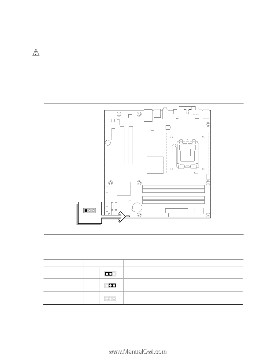
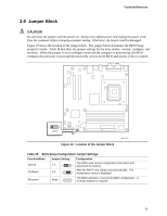
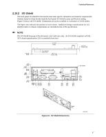
Technical Reference 2.9 Jumper Block CAUTION Do not move the jumper with the power on. Always turn off the power and unplug the power cord from the computer before changing a jumper setting. Otherwise, the board could be damaged. Figure 19 shows the location of the jumper block. The jumper block determines the BIOS Setup program's mode. Table 28 describes the jumper settings for the three modes: normal, configure, and recovery. When the jumper is set to configure mode and the computer is powered-up, the BIOS compares the processor version and the microcode version in the BIOS and reports if the two match. 1 3 J8J4 Figure 19. Location of the Jumper Block OM17810 Table 28. BIOS Setup Configuration Jumper Settings Function/Mode Normal Configure Jumper Setting 1-2 1 3 2-3 1 3 Configuration The BIOS uses current configuration information and passwords for booting. After the POST runs, Setup runs automatically. The maintenance menu is displayed. Recovery None 1 The BIOS attempts to recover the BIOS configuration. A 3 recovery diskette is required. 55
-
 1
1 -
2
-
3
-
4
-
5
-
6
-
7
-
8
-
9
-
10
-
11
-
12
-
13
-
14
-
15
-
16
-
17
-
18
-
19
-
20
-
21
-
22
-
23
-
24
-
25
-
26
-
27
-
28
-
29
-
30
-
31
-
32
-
33
-
34
-
35
-
36
-
37
-
38
-
39
-
40
-
41
-
42
-
43
-
44
-
45
-
46
-
47
-
48
-
49
-
 50
50 -
 51
51 -
 52
52 -
 53
53 -
 54
54 -
 55
55 -
 56
56 -
 57
57 -
 58
58 -
 59
59 -
 60
60 -
61
-
62
-
63
-
64
-
65
-
66
-
67
-
68
-
69
-
70
-
71
-
72
-
73
-
74
-
75
-
76
-
77
-
78
-
79
-
80
-
81
-
82
-
83
-
84
 |
 |