Intel D915GVWB D915GVWB Desktop Board Specification Update - Page 10
Summary Table of Changes, Intel, Desktop Board D915GVWB Specification Update - drivers
 |
View all Intel D915GVWB manuals
Add to My Manuals
Save this manual to your list of manuals |
Page 10 highlights
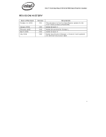
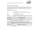
Intel® Desktop Board D915GVWB Specification Update Summary Table of Changes The following table indicates the Specification Changes, Errata, Specification Clarifications, or Documentation Changes that apply to the Intel® Desktop Board D915GVWB. Intel intends to fix some of the errata in a future revision of the desktop board, and to account for the other outstanding issues through documentation or specification changes as noted. This table uses the following notations: CODES USED IN SUMMARY TABLE Doc: Plan Fix: Fixed: No Fix: Shaded: Document change or update that will be implemented. This erratum may be fixed in a future revision of the desktop board, driver, or BIOS. This erratum has been previously fixed. There are no plans to fix this erratum. This erratum is either new or modified from the previous version of the document. NO. PLANS SPECIFICATION CHANGES 1 Doc Changes to Section 2.8.2.2, Add-in Card Connectors NO. PLANS ERRATA 1 Plan Fix The IEEE-1394a interface may lose link connection when transferring files from some IEEE-1394a DVD/CD-ROM devices 2 Plan Fix Wake On LAN may not function after loss and restore of AC power 3 Plan Fix The placement of capacitors behind the PCI Express* x1 connector slot may prohibit some PCI Express x1 Add-in cards from properly connecting to the motherboard NO. PLANS DOCUMENTATION CHANGES 1 Doc Incorrect operating voltage listed for supported memory in Section 1.6, System Memory 4
-
 1
1 -
2
-
3
-
4
-
 5
5 -
 6
6 -
 7
7 -
 8
8 -
 9
9 -
 10
10 -
 11
11 -
 12
12 -
 13
13 -
 14
14
 |
 |