Intel D915PDT English Product Guide - Page 38
Connecting Internal Headers
 |
View all Intel D915PDT manuals
Add to My Manuals
Save this manual to your list of manuals |
Page 38 highlights
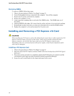
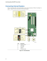
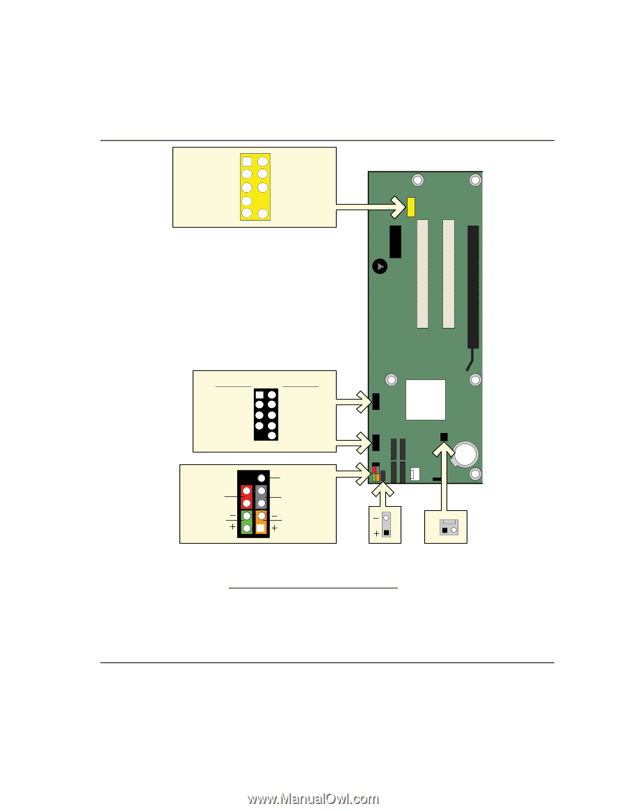
Intel Desktop Board D915PDT Product Guide Connecting Internal Headers Before connecting cables to the internal headers, observe the precautions in "Before You Begin" on 25H page 23. Figure 18 shows the location of the internal headers. 26H 27H Port1L Port1R Port2R Sense_Send Port2L 12 34 56 7 9 10 GND Presence# Sense1_Ret Key (no pin) Sense2_Ret E D USB A Power (+5V) DD+ Ground Key (no pin) USB B 1 2 Power (+5V) 3 4 D5 6 D+ 7 8 Ground 10 N/C 9 +5V On/Off 87 65 Reset Power LED 43 HD LED 3 21 1 C B Item A B C D E Description Chassis intrusion Power LED Front panel USB 2.0 Front panel audio Figure 18. Internal Headers 1 A OM18058 38
-
 1
1 -
2
-
3
-
4
-
5
-
6
-
7
-
8
-
9
-
10
-
11
-
12
-
13
-
14
-
15
-
16
-
17
-
18
-
19
-
20
-
21
-
22
-
23
-
24
-
25
-
26
-
27
-
28
-
29
-
30
-
31
-
32
-
 33
33 -
 34
34 -
 35
35 -
 36
36 -
 37
37 -
 38
38 -
 39
39 -
 40
40 -
 41
41 -
 42
42 -
 43
43 -
44
-
45
-
46
-
47
-
48
-
49
-
50
-
51
-
52
-
53
-
54
-
55
-
56
-
57
-
58
-
59
-
60
-
61
-
62
-
63
-
64
-
65
-
66
-
67
-
68
 |
 |
Intel Desktop Board D915PDT Product Guide
38
Connecting Internal Headers
Before connecting cables to the internal headers, observe the precautions in "
Before You Begin" on
page
23.
Figure 18 shows the location of the internal headers.
OM18058
C
On/Off
Power LED
HD LED
Reset
+5V
1
2
3
4
5
7
6
8
9
B
1
3
D
USB A
USB B
1
5
6
7
8
3
4
2
10
Power (+5V)
Power (+5V)
D-
D+
Ground
Key (no pin)
N/C
D-
D+
Ground
1
5
6
7
3
4
2
10
9
Port1L
Port1R
Port2R
Sense_Send
Port2L
GND
Presence#
Sense1_Ret
Key (no pin)
Sense2_Ret
E
A
1
Item
Description
A
Chassis intrusion
B
Power LED
C
Front panel
D
USB 2.0
E
Front panel audio
Figure 18.
Internal Headers