Intel D945GCNL Product Guide - Page 43
Connecting to the Alternate Front Panel Power LED Header, Connecting to the Flexible Audio System - audio drivers
 |
UPC - 735858194570
View all Intel D945GCNL manuals
Add to My Manuals
Save this manual to your list of manuals |
Page 43 highlights
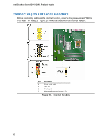
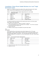
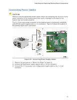
Installing and Replacing Desktop Board Components Connecting to the Alternate Front Panel Power LED Header Figure 20, D on page 40 shows the location of the alternate front panel power LED header. Pins 1 and 3 of this header duplicate the signals on pins 2 and 4 of the front panel header. If your chassis has a three-pin power LED cable, connect it to this header. Table 8 shows the pin assignments for the alternate front panel power LED header. Table 8. Alternate Front Panel Power LED Header Pin Description 1 Front panel green LED 2 No pin 3 Front panel yellow LED In/Out Out Out Connecting to the Flexible Audio System After installing the RealTek audio driver, the multi-channel audio feature can be enabled. Figure 21 shows the back panel audio connectors. The default connector assignments are shown in the table. The connectors are retaskable using the audio driver interface. Item Description A Line in/retasking jack B Line out/retasking jack C Mic in/retasking jack Figure 21. Back Panel Audio Connectors 43
-
 1
1 -
2
-
3
-
4
-
5
-
6
-
7
-
8
-
9
-
10
-
11
-
12
-
13
-
14
-
15
-
16
-
17
-
18
-
19
-
20
-
21
-
22
-
23
-
24
-
25
-
26
-
27
-
28
-
29
-
30
-
31
-
32
-
33
-
34
-
35
-
36
-
37
-
 38
38 -
 39
39 -
 40
40 -
 41
41 -
 42
42 -
 43
43 -
 44
44 -
 45
45 -
 46
46 -
 47
47 -
 48
48 -
49
-
50
-
51
-
52
-
53
-
54
-
55
-
56
-
57
-
58
-
59
-
60
-
61
-
62
-
63
-
64
-
65
-
66
-
67
-
68
 |
 |
