Intel D945GNTLKR Product Guide - Page 45
Connecting Hi-Speed USB 2.0 Headers, Connecting IEEE 1394a Headers (Optional), Table 11.
 |
UPC - 735858174671
View all Intel D945GNTLKR manuals
Add to My Manuals
Save this manual to your list of manuals |
Page 45 highlights
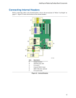
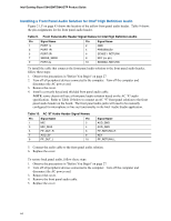
Installing and Replacing Desktop Board Components Connecting Hi-Speed USB 2.0 Headers Before connecting the USB 2.0 headers, observe the precautions in "Before You Begin" on page 27. See Figure 21, D on page 43 for the location of the black USB 2.0 headers. Table 11 shows the pin assignments for the headers. Table 11. Hi-Speed USB 2.0 Header Signal Names USB Port A Pin Signal name Pin 1 Power 2 3 D- 4 5 D+ 6 7 Ground 8 9 Key 10 Note: USB ports may be assigned as needed. USB Port B Signal name Power DD+ Ground No connect Connecting IEEE 1394a Headers (Optional) Before connecting the IEEE 1394a headers, observe the precautions in "Before You Begin" on page 27. See Figure 21, E on page 43 for the location of the blue IEEE 1394a headers. Table 12 shows the pin assignments for the headers. Table 12. IEEE 1394a Header Signal Names Pin Signal Name Pin 1 TPA1+ 2 3 Ground 4 5 TPA2+ 6 7 +12 V 8 9 Key (no pin) 10 Signal Name TPA1Ground TPA2+12 V Ground 45
-
 1
1 -
2
-
3
-
4
-
5
-
6
-
7
-
8
-
9
-
10
-
11
-
12
-
13
-
14
-
15
-
16
-
17
-
18
-
19
-
20
-
21
-
22
-
23
-
24
-
25
-
26
-
27
-
28
-
29
-
30
-
31
-
32
-
33
-
34
-
35
-
36
-
37
-
38
-
39
-
 40
40 -
 41
41 -
 42
42 -
 43
43 -
 44
44 -
 45
45 -
 46
46 -
 47
47 -
 48
48 -
 49
49 -
 50
50 -
51
-
52
-
53
-
54
-
55
-
56
-
57
-
58
-
59
-
60
-
61
-
62
-
63
-
64
-
65
-
66
-
67
-
68
-
69
-
70
-
71
-
72
-
73
-
74
 |
 |
