Intel DG45FC Product Guide - Page 43
USB 2.0 Headers, Table 7. Front Panel CIR Receiver Input Header Signal Names
 |
UPC - 735858200417
View all Intel DG45FC manuals
Add to My Manuals
Save this manual to your list of manuals |
Page 43 highlights
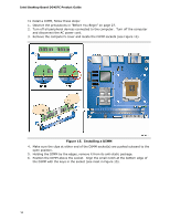
Installing and Replacing Desktop Board Components NOTE The Consumer IR option must be enabled in the system BIOS before it can function. Press at boot to enter the system BIOS, and go to Advanced > Peripheral Configuration > Enhanced Consumer IR, and set this option to Enabled. Table 7 shows the pin assignments for the front panel CIR receiver (input) header and Table 8 shows the pin assignments for the back panel CIR emitter (output) header. Table 7. Front Panel CIR Receiver (Input) Header Signal Names Pin Signal Name 1 Ground 3 No Connection 5 +5 V Standby 7 Key (no pin) Pin Signal Name 2 LED 4 Learn-In 6 Vcc 8 CIR Input Table 8. Back Panel CIR Emitter (Output) Header Signal Names Pin Signal Name 1 Emitter Out 1 3 Ground 5 Jack Detect 1 Pin Signal Name 2 Emitter Out 2 4 Key (no pin) 6 Jack Detect 2 USB 2.0 Headers See Figure 17, D for the location of the two USB 2.0 headers. Table 9 shows the pin assignments for each USB 2.0 header. Each USB header can be used to connect two USB devices. Table 9. USB 2.0 Header Signal Names USB Port A Pin Signal Name Pin 1 Power (+5 V) 2 3 D- 4 5 D+ 6 7 Ground 8 9 Key 10 Note: USB ports may be assigned as needed. USB Port B Signal Name Power (+5 V) DD+ Ground No Connection NOTE Computer systems that have an unshielded cable attached to a USB port might not meet FCC Class B requirements, even if no device or a low-speed USB device is attached to the cable. Use a shielded cable that meets the requirements for a full-speed USB device. 43
-
 1
1 -
2
-
3
-
4
-
5
-
6
-
7
-
8
-
9
-
10
-
11
-
12
-
13
-
14
-
15
-
16
-
17
-
18
-
19
-
20
-
21
-
22
-
23
-
24
-
25
-
26
-
27
-
28
-
29
-
30
-
31
-
32
-
33
-
34
-
35
-
36
-
37
-
 38
38 -
 39
39 -
 40
40 -
 41
41 -
 42
42 -
 43
43 -
 44
44 -
 45
45 -
 46
46 -
 47
47 -
 48
48 -
49
-
50
-
51
-
52
-
53
-
54
-
55
-
56
-
57
-
58
-
59
-
60
-
61
-
62
-
63
-
64
-
65
-
66
-
67
-
68
-
69
-
70
-
71
-
72
-
73
-
74
-
75
-
76
-
77
-
78
-
79
-
80
 |
 |