Intel DG45ID Product Guide - Page 49
IEEE 1394a Header, Connecting to the Audio System - audio driver
 |
UPC - 735858200387
View all Intel DG45ID manuals
Add to My Manuals
Save this manual to your list of manuals |
Page 49 highlights
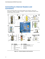
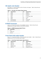
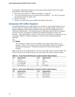
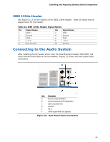
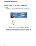
Installing and Replacing Desktop Board Components IEEE 1394a Header See Figure 21, K for the location of the IEEE 1394a header. Table 15 shows the pin assignments for the header. Table 15. IEEE 1394a Header Signal Names Pin Signal Name 1 TPA1+ 3 Ground 5 TPA2+ 7 +12 V 9 Key (no pin) Pin Signal Name 2 TPA1- 4 Ground 6 TPA2- 8 +12 V 10 Ground Connecting to the Audio System After installing the IDT audio driver from the Intel Express Installer DVD-ROM, the multi-channel audio feature can be enabled. Figure 22 shows the back panel audio connectors. Item Description A Rear Surround Left/Right B Center Channel and LFE (Subwoofer) C Side Surround/Line In D Line Out E Mic In F S/PDIF Digital Audio Out (Optical) Figure 22. Back Panel Audio Connectors 49
-
 1
1 -
2
-
3
-
4
-
5
-
6
-
7
-
8
-
9
-
10
-
11
-
12
-
13
-
14
-
15
-
16
-
17
-
18
-
19
-
20
-
21
-
22
-
23
-
24
-
25
-
26
-
27
-
28
-
29
-
30
-
31
-
32
-
33
-
34
-
35
-
36
-
37
-
38
-
39
-
40
-
41
-
42
-
43
-
 44
44 -
 45
45 -
 46
46 -
 47
47 -
 48
48 -
 49
49 -
 50
50 -
 51
51 -
 52
52 -
 53
53 -
 54
54 -
55
-
56
-
57
-
58
-
59
-
60
-
61
-
62
-
63
-
64
-
65
-
66
-
67
-
68
-
69
-
70
-
71
-
72
-
73
-
74
-
75
-
76
-
77
-
78
-
79
-
80
-
81
-
82
-
83
-
84
-
85
-
86
 |
 |
