Intel DH55TC Product Guide - Page 7

Intel Desktop Board DH55TC China RoHS Material Self Declaration Table - memory configuration

Page 7 highlights

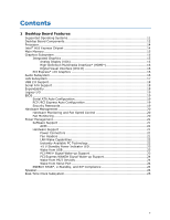
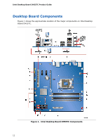
Contents A Error Messages and Indicators BIOS Error Codes 67 BIOS Error Messages 68 B Regulatory Compliance Safety Standards 69 Place Battery Marking 69 European Union Declaration of Conformity Statement 70 Product Ecology Statements 71 Recycling Considerations 71 Lead-free 2LI/Pb-free 2LI Board 74 Restriction of Hazardous Substances (RoHS 75 EU RoHS 75 China RoHS 76 EMC Regulations 78 Ensure Electromagnetic Compatibility (EMC) Compliance 79 Product Certifications 80 Board-Level Certification Markings 80 Chassis and Component Certifications 81 Figures 1. Intel Desktop Board DH55TC Components 12 2. LAN Connector LEDs 17 3. Location of the Standby Power Indicator 23 4. Installing the I/O Shield 29 5. Intel Desktop Board DH55TC Mounting Screw Hole Locations 30 6. Unlatch the Socket Lever 31 7. Lift the Load Plate 32 8. Remove the Socket Cover 33 9. Remove the Processor from the Protective Cover 34 10. Install the Processor 34 11. Lower the Load Plate 35 12. Secure the Load Plate in Place 35 13. Connecting the Processor Fan Heat Sink Power Cable to the Processor Fan Header 36 14. Example Dual Channel Memory Configuration with Two DIMMs 37 15. Example Dual Channel Memory Configuration with Four DIMMs 38 16. Example Dual Channel Memory Configuration with Three DIMMs 38 17. Use DDR3 DIMMs 39 18. Installing a DIMM 40 19. Installing a PCI Express x16 Graphics Card 42 20. Removing a PCI Express x16 Graphics Card 43 21. Connecting a Serial ATA Cable 44 22. Installing an Intel Z-U130 USB Solid-State Drive (or Compatible Device 45 23. Internal Headers 46 24. Back Panel Audio Connectors 51 25. Location of the Chassis Fan Headers 52 26. Connecting Power Supply Cables 53 27. Location of the BIOS Configuration Jumper Block 54 28. Removing the Battery 61 29. Intel Desktop Board DH55TC China RoHS Material Self Declaration Table 77 vii

  • 1
  • 2
  • 3
  • 4
  • 5
  • 6
  • 7
  • 8
  • 9
  • 10
  • 11
  • 12
  • 13
  • 14
  • 15
  • 16
  • 17
  • 18
  • 19
  • 20
  • 21
  • 22
  • 23
  • 24
  • 25
  • 26
  • 27
  • 28
  • 29
  • 30
  • 31
  • 32
  • 33
  • 34
  • 35
  • 36
  • 37
  • 38
  • 39
  • 40
  • 41
  • 42
  • 43
  • 44
  • 45
  • 46
  • 47
  • 48
  • 49
  • 50
  • 51
  • 52
  • 53
  • 54
  • 55
  • 56
  • 57
  • 58
  • 59
  • 60
  • 61
  • 62
  • 63
  • 64
  • 65
  • 66
  • 67
  • 68
  • 69
  • 70
  • 71
  • 72
  • 73
  • 74
  • 75
  • 76
  • 77
  • 78
  • 79
  • 80
  • 81
  • 82

Contents
vii
A
Error Messages and Indicators
BIOS Error Codes
...............................................................................................
67
BIOS Error Messages
..........................................................................................
68
B
Regulatory Compliance
Safety Standards
...............................................................................................
69
Place Battery Marking
.................................................................................
69
European Union Declaration of Conformity Statement
..............................................
70
Product Ecology Statements
................................................................................
71
Recycling Considerations
.............................................................................
71
Lead-free 2LI/Pb-free 2LI Board
...................................................................
74
Restriction of Hazardous Substances (RoHS)
..................................................
75
EU RoHS
............................................................................................
75
China RoHS
........................................................................................
76
EMC Regulations
................................................................................................
78
Ensure Electromagnetic Compatibility (EMC) Compliance
..................................
79
Product Certifications
..........................................................................................
80
Board-Level Certification Markings
................................................................
80
Chassis and Component Certifications
............................................................
81
Figures
1. Intel Desktop Board DH55TC Components
........................................................
12
2. LAN Connector LEDs
.....................................................................................
17
3.
Location of the Standby Power Indicator
..........................................................
23
4. Installing the I/O Shield
................................................................................
29
5.
Intel Desktop Board DH55TC Mounting Screw Hole Locations
..............................
30
6. Unlatch the Socket Lever
...............................................................................
31
7. Lift the Load Plate
.........................................................................................
32
8. Remove the Socket Cover
..............................................................................
33
9.
Remove the Processor from the Protective Cover
..............................................
34
10. Install the Processor
.....................................................................................
34
11. Lower the Load Plate
.....................................................................................
35
12. Secure the Load Plate in Place
........................................................................
35
13. Connecting the Processor Fan Heat Sink Power Cable
to the Processor Fan Header
..........................................................................
36
14. Example Dual Channel Memory Configuration with Two DIMMs
...........................
37
15. Example Dual Channel Memory Configuration with Four DIMMs
...........................
38
16. Example Dual Channel Memory Configuration with Three DIMMs
.........................
38
17. Use DDR3 DIMMs
.........................................................................................
39
18. Installing a DIMM
.........................................................................................
40
19. Installing a PCI Express x16 Graphics Card
......................................................
42
20. Removing a PCI Express x16 Graphics Card
......................................................
43
21. Connecting a Serial ATA Cable
........................................................................
44
22. Installing an Intel Z-U130 USB Solid-State Drive (or Compatible Device)
..............
45
23. Internal Headers
..........................................................................................
46
24. Back Panel Audio Connectors
.........................................................................
51
25. Location of the Chassis Fan Headers
................................................................
52
26. Connecting Power Supply Cables
....................................................................
53
27. Location of the BIOS Configuration Jumper Block
..............................................
54
28. Removing the Battery
...................................................................................
61
29. Intel Desktop Board DH55TC China RoHS Material Self Declaration Table
..............
77