Intel DH61BE English Product Guide - Page 48
TPM Header, Front Panel Header, Table 9. TPM Header Signal Names
 |
View all Intel DH61BE manuals
Add to My Manuals
Save this manual to your list of manuals |
Page 48 highlights
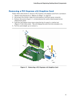
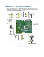
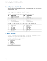
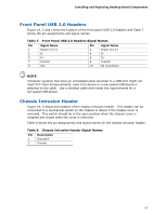
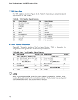
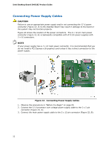
Intel Desktop Board DH61BE Product Guide TPM Header The TPM header is shown in Figure 19, E. Table 9 shows the pin assignments and signal names for TPM header. Table 9. TPM Header Signal Names Pin Signal Name Pin 1 CK_33M_TPM_DIP 2 3 LFRAME# 4 5 PLTRST# 6 7 LAD3 8 9 +3.3 V 10 11 LAD0 12 13 No connection 14 15 +3.3 VSB 16 17 Ground 18 19 LPCPD# 20 Signal Name Ground Key (no pin) No connection LAD2 LAD1 Ground No connection TPM_SERRQ TPM_CLKRUN# No connection Front Panel Header Figure 19, F shows the location of the front panel header. Table 10 shows the pin assignments and signal names for the front panel header. Table 10. Front Panel Header Signal Names Pin Description In/Out Pin Description Hard Disk Drive Activity LED Power LED 1 Hard disk LED pull-up to +5 V Out 2 Front panel LED+ 3 Hard disk active LED Out 4 Front panel LED- Reset Switch On/Off Switch 5 Ground 6 Power switch 7 Reset switch In 8 Ground Power Not Connected 9 Power Out 10 No pin In/Out Out Out In NOTE When connecting individual wires from your chassis front panel to the front panel header, be sure to observe the connection polarity. Positive wires are usually solid color and negative wires are usually white or striped. 48
-
 1
1 -
2
-
3
-
4
-
5
-
6
-
7
-
8
-
9
-
10
-
11
-
12
-
13
-
14
-
15
-
16
-
17
-
18
-
19
-
20
-
21
-
22
-
23
-
24
-
25
-
26
-
27
-
28
-
29
-
30
-
31
-
32
-
33
-
34
-
35
-
36
-
37
-
38
-
39
-
40
-
41
-
42
-
 43
43 -
 44
44 -
 45
45 -
 46
46 -
 47
47 -
 48
48 -
 49
49 -
 50
50 -
 51
51 -
 52
52 -
 53
53 -
54
-
55
-
56
-
57
-
58
-
59
-
60
-
61
-
62
-
63
-
64
-
65
-
66
-
67
-
68
-
69
-
70
-
71
-
72
-
73
-
74
-
75
-
76
-
77
-
78
-
79
-
80
 |
 |
