Intel DH77KC Technical Product Specification - Page 53
Add-in Card Connectors, 2.2.3, Power Supply Connectors - compatible processors
 |
View all Intel DH77KC manuals
Add to My Manuals
Save this manual to your list of manuals |
Page 53 highlights
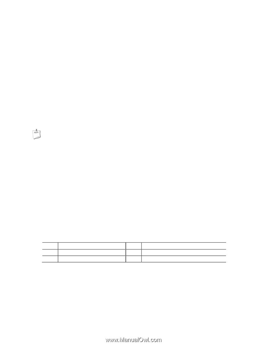
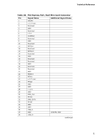
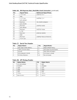
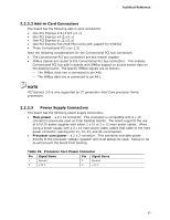
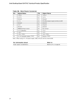
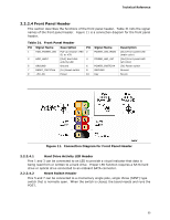
Technical Reference 2.2.2.2 Add-in Card Connectors The board has the following add-in card connectors: • One PCI Express x16 (3.0/2.x/1.x) • One PCI Express x4 (2.x/1.x) • One PCI Express x1 (2.x/1.x) • One PCI Express Full-/Half-Mini Card (with support for mSATA) • Three Conventional PCI (rev 2.3) Note the following considerations for the Conventional PCI bus connectors: • The Conventional PCI bus connectors are bus master capable. • SMBus signals are routed to the Conventional PCI bus connectors. This enables Conventional PCI bus add-in boards with SMBus support to access sensor data on the desktop board. The specific SMBus signals are as follows: ⎯ The SMBus clock line is connected to pin A40. ⎯ The SMBus data line is connected to pin A41. NOTE PCI Express 3.0 is only supported by 3rd generation Intel Core processor family processors. 2.2.2.3 Power Supply Connectors The board has the following power supply connectors: • Main power - a 2 x 12 connector. This connector is compatible with 2 x 10 connectors previously used on Intel Desktop boards. The board supports the use of ATX12V power supplies with either 2 x 10 or 2 x 12 main power cables. When using a power supply with a 2 x 10 main power cable, attach that cable to the main power connector, leaving pins 11, 12, 23, and 24 unconnected. • Processor core power - a 2 x 2 connector. This connector provides power directly to the processor voltage regulator and must always be used. Failure to do so will prevent the board from booting. Table 29. Processor Core Power Connector Pin Signal Name Pin Signal Name 1 Ground 2 Ground 3 +12 V 4 +12 V 53
-
 1
1 -
2
-
3
-
4
-
5
-
6
-
7
-
8
-
9
-
10
-
11
-
12
-
13
-
14
-
15
-
16
-
17
-
18
-
19
-
20
-
21
-
22
-
23
-
24
-
25
-
26
-
27
-
28
-
29
-
30
-
31
-
32
-
33
-
34
-
35
-
36
-
37
-
38
-
39
-
40
-
41
-
42
-
43
-
44
-
45
-
46
-
47
-
 48
48 -
 49
49 -
 50
50 -
 51
51 -
 52
52 -
 53
53 -
 54
54 -
 55
55 -
 56
56 -
 57
57 -
 58
58 -
59
-
60
-
61
-
62
-
63
-
64
-
65
-
66
-
67
-
68
-
69
-
70
-
71
-
72
-
73
-
74
-
75
-
76
-
77
-
78
-
79
-
80
-
81
-
82
-
83
-
84
-
85
-
86
-
87
-
88
-
89
-
90
-
91
-
92
-
93
-
94
-
95
-
96
-
97
-
98
-
99
 |
 |