Intel DP43TF Product Guide - Page 45
HD Audio Link Header, S/PDIF Connector, Chassis Intrusion Header
 |
UPC - 735858202046
View all Intel DP43TF manuals
Add to My Manuals
Save this manual to your list of manuals |
Page 45 highlights
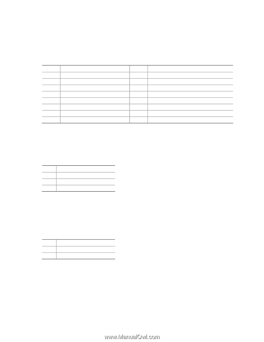
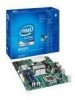
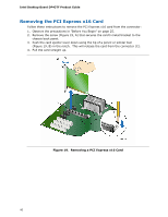
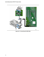
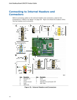
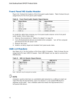
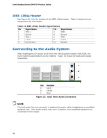
Installing and Replacing Desktop Board Components HD Audio Link Header See Figure 22, A for the location of the HD Audio Link header. Table 5 shows the pin assignments for the header. Table 5. HD Audio Link Header Signal Names Pin Signal Name 1 BCLK 3 RST# Pin Signal Name 2 Ground 4 DVDD_IO 5 SYNC 6 Ground 7 SDO 9 SDI0 11 SDI1 8 3.3V_DVDD_CORE 10 +12 V 12 Key 13 No Connection 14 3.3V_DUAL 15 No Connection 16 Ground S/PDIF Connector Figure 22, B shows the location of the S/PDIF connector. Table 6 shows the pin assignments and signal names for the S/PDIF connector. Table 6. S/PDIF Connector Signal Names Pin Description 1 Vcc 2 S/PDIF Out 3 Ground Chassis Intrusion Header Figure 22, C on page 44 shows the location of the chassis intrusion header. This header can be connected to a mechanical switch on the chassis to detect if the chassis cover is removed. Table 7 shows the pin assignments for the chassis intrusion header. Table 7. Chassis Intrusion Header Signal Names Pin Description 1 Intruder 2 Ground 45
-
 1
1 -
2
-
3
-
4
-
5
-
6
-
7
-
8
-
9
-
10
-
11
-
12
-
13
-
14
-
15
-
16
-
17
-
18
-
19
-
20
-
21
-
22
-
23
-
24
-
25
-
26
-
27
-
28
-
29
-
30
-
31
-
32
-
33
-
34
-
35
-
36
-
37
-
38
-
39
-
 40
40 -
 41
41 -
 42
42 -
 43
43 -
 44
44 -
 45
45 -
 46
46 -
 47
47 -
 48
48 -
 49
49 -
 50
50 -
51
-
52
-
53
-
54
-
55
-
56
-
57
-
58
-
59
-
60
-
61
-
62
-
63
-
64
-
65
-
66
-
67
-
68
-
69
-
70
-
71
-
72
-
73
-
74
-
75
-
76
-
77
-
78
 |
 |