Intel DP67DE English Product Guide - Page 28
Installing and Removing the Desktop Board,
 |
View all Intel DP67DE manuals
Add to My Manuals
Save this manual to your list of manuals |
Page 28 highlights
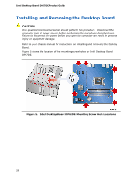
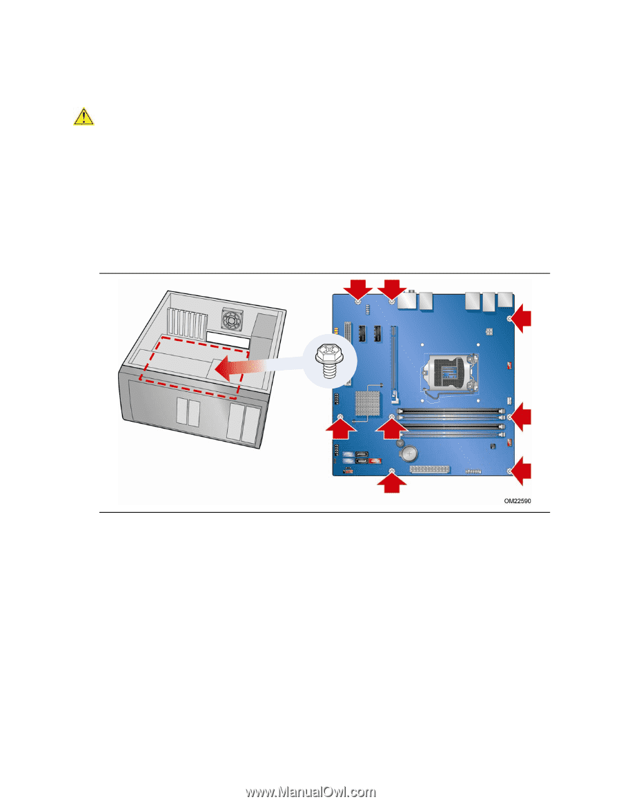
Intel Desktop Board DP67DE Product Guide Installing and Removing the Desktop Board CAUTION Only qualified technical personnel should perform this procedure. Disconnect the computer from its power source before performing the procedures described here. Failure to disconnect the power before you open the computer can result in personal injury or equipment damage. Refer to your chassis manual for instructions on installing and removing the Desktop Board. Figure 5 shows the location of the mounting screw holes for Intel Desktop Board DP67DE. Figure 5. Intel Desktop Board DP67DE Mounting Screw Hole Locations 28
-
 1
1 -
2
-
3
-
4
-
5
-
6
-
7
-
8
-
9
-
10
-
11
-
12
-
13
-
14
-
15
-
16
-
17
-
18
-
19
-
20
-
21
-
22
-
 23
23 -
 24
24 -
 25
25 -
 26
26 -
 27
27 -
 28
28 -
 29
29 -
 30
30 -
 31
31 -
 32
32 -
 33
33 -
34
-
35
-
36
-
37
-
38
-
39
-
40
-
41
-
42
-
43
-
44
-
45
-
46
-
47
-
48
-
49
-
50
-
51
-
52
-
53
-
54
-
55
-
56
-
57
-
58
-
59
-
60
-
61
-
62
-
63
-
64
-
65
-
66
-
67
-
68
-
69
-
70
-
71
-
72
-
73
-
74
-
75
-
76
-
77
-
78
 |
 |
Intel Desktop Board DP67DE Product Guide
28
Installing and Removing the Desktop Board
CAUTION
Only qualified technical personnel should perform this procedure.
Disconnect the
computer from its power source before performing the procedures described here.
Failure to disconnect the power before you open the computer can result in personal
injury or equipment damage.
Refer to your chassis manual for instructions on installing and removing the Desktop
Board.
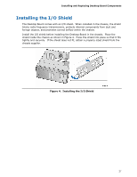
Figure 5 shows the location of the mounting screw holes for Intel Desktop Board
DP67DE.
Figure 5.
Intel Desktop Board DP67DE Mounting Screw Hole Locations