Intel DQ35JOE Product Specification - Page 43
Connectors and Headers
 |
UPC - 675900868960
View all Intel DQ35JOE manuals
Add to My Manuals
Save this manual to your list of manuals |
Page 43 highlights
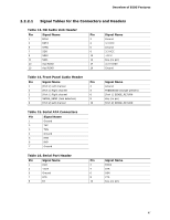
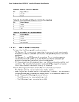
Overview of BIOS Features Table 11 lists the system memory map. Table 11. System Memory Map Address Range (decimal) Address Range (hex) 1024 K - 8388608 K 100000 - 1FFFFFFFF 960 K - 1024 K F0000 - FFFFF 896 K - 960 K 800 K - 896 K E0000 - EFFFF C8000 - DFFFF 640 K - 800 K 639 K - 640 K 512 K - 639 K 0 K - 512 K A0000 - C7FFF 9FC00 - 9FFFF 80000 - 9FBFF 00000 - 7FFFF Size 8191 MB 64 KB 64 KB 96 KB 160 KB 1 KB 127 KB 512 KB Description Extended memory Runtime BIOS Reserved Potential available high DOS memory (open to the PCI bus). Dependent on video adapter used. Video memory and BIOS Extended BIOS data (movable by memory manager software) Extended conventional memory Conventional memory 2.2 Connectors and Headers CAUTION Only the following connectors and headers have overcurrent protection: Back panel and front panel USB. The other internal connectors/headers are not overcurrent protected and should connect only to devices inside the computer's chassis, such as fans and internal peripherals. Do not use these connectors/headers to power devices external to the computer's chassis. A fault in the load presented by the external devices could cause damage to the computer, the power cable, and the external devices themselves. NOTE Computer systems that have an unshielded cable attached to a USB port may not meet FCC Class B requirements, even if no device is attached to the cable. Use shielded cable that meets the requirements for full-speed devices. This section describes the board's connectors and headers. The connectors and headers can be divided into these groups: • Back panel I/O connectors (see page 44) • Component-side connectors and headers (see page 45) 43
-
 1
1 -
2
-
3
-
4
-
5
-
6
-
7
-
8
-
9
-
10
-
11
-
12
-
13
-
14
-
15
-
16
-
17
-
18
-
19
-
20
-
21
-
22
-
23
-
24
-
25
-
26
-
27
-
28
-
29
-
30
-
31
-
32
-
33
-
34
-
35
-
36
-
37
-
 38
38 -
 39
39 -
 40
40 -
 41
41 -
 42
42 -
 43
43 -
 44
44 -
 45
45 -
 46
46 -
 47
47 -
 48
48 -
49
-
50
-
51
-
52
-
53
-
54
-
55
-
56
-
57
-
58
-
59
-
60
-
61
-
62
-
63
-
64
-
65
-
66
-
67
-
68
-
69
-
70
-
71
-
72
-
73
-
74
-
75
-
76
-
77
-
78
-
79
-
80
-
81
-
82
-
83
-
84
 |
 |
