Intel DQ77KB Technical Product Specification - Page 63
Add-in Card Connectors, 2.3.3, Power Supply Connectors - alternative
 |
View all Intel DQ77KB manuals
Add to My Manuals
Save this manual to your list of manuals |
Page 63 highlights
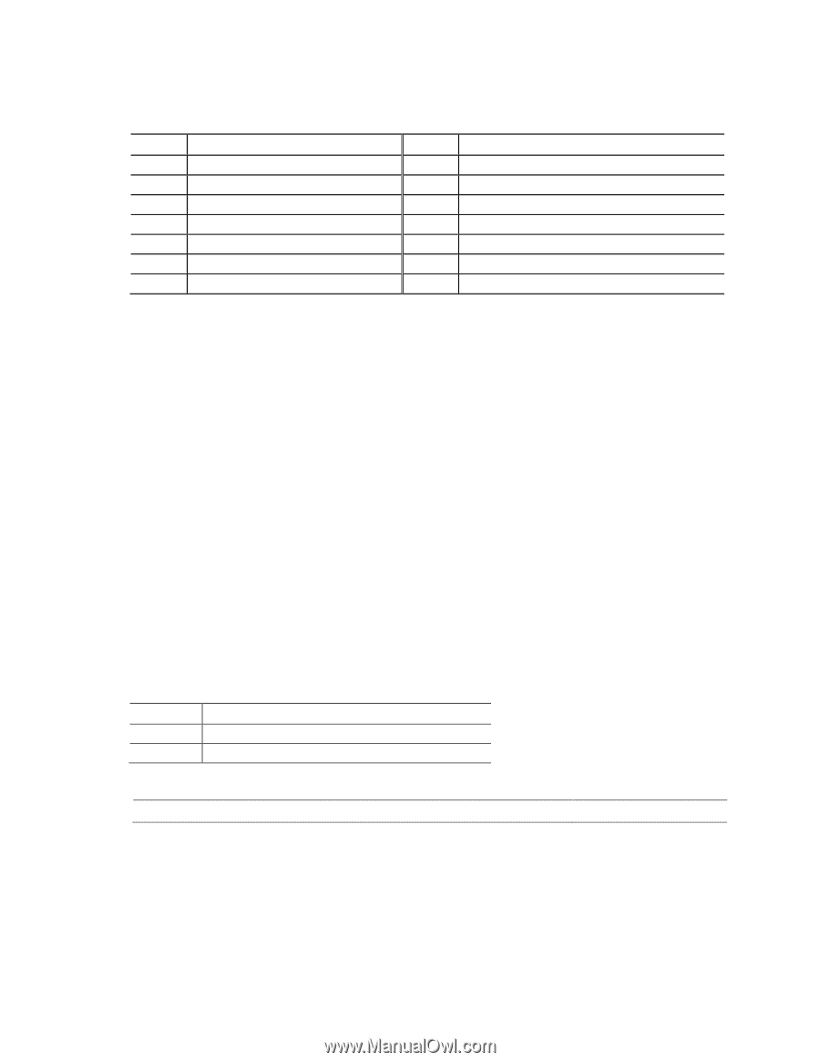
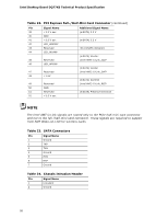
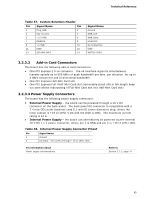
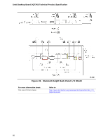
Technical Reference Table 37. Custom Solutions Header Pin Signal Name Pin 1 Prog_LED 2 3 Key (no pin) 4 5 +3.3 VSB 6 7 PWRBT# 8 9 +5 VSB 10 11 USB+ 12 13 SCI/SMI GPIO 14 Signal Name Ground SMB_CLK SMB_Data HDM CEC No Connection USB− WDTO#/GPIO 2.2.3.2 Add-in Card Connectors The board has the following add-in card connectors: • One PCI Express 2.0 x4 connector. The x4 interface supports simultaneous transfer speeds up to 500 MB/s of peak bandwidth per lane, per direction, for up to 4 GB/s concurrent and bi-directional bandwidth. • One PCI Express Half-Mini Card slot • One PCI Express Full-/Half-Mini Card slot (removable stand-offs in full-length keep out zone allows repurposing of Full-Mini Card slot into Half-Mini Card slot) 2.2.3.3 Power Supply Connectors The board has the following power supply connectors: • External Power Supply - the board can be powered through a 19 V DC connector on the back panel. The back panel DC connector is compatible with a 7.4 mm/OD (outer diameter) and 5.1 mm/ID (inner diameter) plug, where the inner contact is +19 (±10%) V DC and the shell is GND. The maximum current rating is 12 A. • Internal Power Supply - the board can alternatively be powered via the internal 19 V DC 1 x 2 power connector, where pin 1 is GND and pin 2 is +19 (±10%) VDC. Table 38. Internal Power Supply Connector Pinout Pin Signal Name 1 Ground 2 DC input: +8 (±10%) through +19 (±10%) VDC For information about Power supply considerations Refer to Section 2.7.1, page 74 63
-
 1
1 -
2
-
3
-
4
-
5
-
6
-
7
-
8
-
9
-
10
-
11
-
12
-
13
-
14
-
15
-
16
-
17
-
18
-
19
-
20
-
21
-
22
-
23
-
24
-
25
-
26
-
27
-
28
-
29
-
30
-
31
-
32
-
33
-
34
-
35
-
36
-
37
-
38
-
39
-
40
-
41
-
42
-
43
-
44
-
45
-
46
-
47
-
48
-
49
-
50
-
51
-
52
-
53
-
54
-
55
-
56
-
57
-
 58
58 -
 59
59 -
 60
60 -
 61
61 -
 62
62 -
 63
63 -
 64
64 -
 65
65 -
 66
66 -
 67
67 -
 68
68 -
69
-
70
-
71
-
72
-
73
-
74
-
75
-
76
-
77
-
78
-
79
-
80
-
81
-
82
-
83
-
84
-
85
-
86
-
87
-
88
-
89
-
90
-
91
-
92
-
93
-
94
-
95
-
96
-
97
-
98
-
99
-
100
-
101
-
102
-
103
-
104
-
105
-
106
-
107
-
108
-
109
-
110
-
111
-
112
-
113
-
114
 |
 |