Intel E6420 Design Guidelines - Page 43
Table 5-2. Acoustic Targets - power supply
 |
UPC - 735858192569
View all Intel E6420 manuals
Add to My Manuals
Save this manual to your list of manuals |
Page 43 highlights
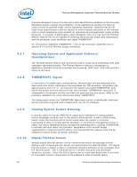
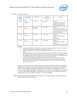
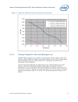
Balanced Technology Extended (BTX) Thermal/Mechanical Design Information Table 5-2. Acoustic Targets Fan Speed RPM Thermistor Set Point Acoustic Thermal Requirements, ca Notes ~ 5300 High TA 35 °C 6.4 BA ~ 2500 Low TA = 23 °C No Target Defined 0.38 C/W 0.56 C/W ~ 1400 Low TA = 23 °C ~ 1400 Low TA = 23 °C 3.4 BA 4.0 BA ~0.87 C/W ~0.87 C/W Case 1: Thermal Design Power Maximum fan speed 100% PWM duty cycle Case 2 Thermal Design Power System (PSU, HDD, TMA) Fan speed limited by the fan hub thermistor Case 3 50% Thermal Design Power TMA Only Case 3 50% Thermal Design Power System (PSU, HDD, TMA) NOTES: 1. Acoustic performance is defined in terms of measured sound power (LwA) as defined in ISO 9296 standard, and measured according to ISO 7779. 2. Acoustic testing will be for the TMA only when installed in a BTX S2 chassis for Case 1 and 3 3. Acoustics testing for Case 2 will be system level in the same a BTX S2 reference chassis and commercially available power supply. Acoustic data for Case 2 will be provided in the validation report but this condition is not a target for the design. The acoustic model is predicting that the power supply fan will be the acoustic limiter. 4. The fan speeds (RPM) are estimates for one of the two reference fans and will be adjusted to meet thermal performance targets then acoustic target during validation. The designer should identify the fan speed required to meet the effective fan curve shown in Section 5.1.3 While the fan hub thermistor helps optimize acoustics at high processor workloads by adapting the maximum fan speed to support the processor thermal profile, additional acoustic improvements can be achieved at lower processor workload by using the TCONTROL specifications described in Section 2.2.3. Intel's recommendation is to use the fan with 4 Wire PWM Controlled to implement fan speed control capability based the digital thermal sensor. Refer to Chapter 7 for further details. Note: Appendix G gives detailed fan performance for the Intel reference thermal solutions with 4 Wire PWM Controlled fan. Thermal and Mechanical Design Guidelines 43
-
 1
1 -
2
-
3
-
4
-
5
-
6
-
7
-
8
-
9
-
10
-
11
-
12
-
13
-
14
-
15
-
16
-
17
-
18
-
19
-
20
-
21
-
22
-
23
-
24
-
25
-
26
-
27
-
28
-
29
-
30
-
31
-
32
-
33
-
34
-
35
-
36
-
37
-
 38
38 -
 39
39 -
 40
40 -
 41
41 -
 42
42 -
 43
43 -
 44
44 -
 45
45 -
 46
46 -
 47
47 -
 48
48 -
49
-
50
-
51
-
52
-
53
-
54
-
55
-
56
-
57
-
58
-
59
-
60
-
61
-
62
-
63
-
64
-
65
-
66
-
67
-
68
-
69
-
70
-
71
-
72
-
73
-
74
-
75
-
76
-
77
-
78
-
79
-
80
-
81
-
82
-
83
-
84
-
85
-
86
-
87
-
88
-
89
-
90
-
91
-
92
-
93
-
94
-
95
-
96
-
97
-
98
-
99
-
100
-
101
-
102
-
103
-
104
-
105
-
106
-
107
-
108
-
109
-
110
-
111
-
112
-
113
-
114
-
115
-
116
-
117
-
118
-
119
-
120
-
121
-
122
-
123
-
124
-
125
-
126
-
127
-
128
-
129
-
130
-
131
-
132
-
133
-
134
-
135
-
136
-
137
-
138
-
139
-
140
-
141
-
142
-
143
-
144
-
145
-
146
-
147
-
148
 |
 |
