Intel HH80557PH0462M Mechanical Design Guidelines - Page 5

Metric for Heatsink Preload for ATX/uATX Designs Non-Compliant with Intel

Page 5 highlights

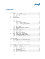
Appendix A Appendix B Appendix C Appendix D Appendix E Appendix F Appendix G Appendix H 7.3 Intel® QST Configuration and Tuning 68 7.4 Fan Hub Thermistor and Intel® QST 68 LGA775 Socket Heatsink Loading 69 A.1 LGA775 Socket Heatsink Considerations 69 A.2 Metric for Heatsink Preload for ATX/uATX Designs Non-Compliant with Intel® Reference Design 69 A.3 Heatsink Preload Requirement Limitations 69 A.3.1 Motherboard Deflection Metric Definition 70 A.3.2 Board Deflection Limits 71 A.3.3 Board Deflection Metric Implementation Example 72 A.3.4 Additional Considerations 73 A.3.4.1 Motherboard Stiffening Considerations 74 A.4 Heatsink Selection Guidelines 74 Heatsink Clip Load Metrology 75 B.1 Overview 75 B.2 Test Preparation 75 B.2.1 Heatsink Preparation 75 B.2.2 Typical Test Equipment 78 B.3 Test Procedure Examples 78 B.3.1 Time-Zero, Room Temperature Preload Measurement 79 B.3.2 Preload Degradation under Bake Conditions 79 Thermal Interface Management 81 C.1 Bond Line Management 81 C.2 Interface Material Area 81 C.3 Interface Material Performance 81 Case Temperature Reference Metrology 83 D.1 Objective and Scope 83 D.2 Supporting Test Equipment 83 D.3 Thermal Calibration and Controls 85 D.4 IHS Groove 85 D.5 Thermocouple Attach Procedure 89 D.5.1 Thermocouple Conditioning and Preparation 89 D.5.2 Thermocouple Attachment to the IHS 90 D.5.3 Solder Process 95 D.5.4 Cleaning and Completion of Thermocouple Installation 98 D.6 Thermocouple Wire Management 102 Balanced Technology Extended (BTX) System Thermal Considerations 103 Fan Performance for Reference Design 107 Mechanical Drawings 109 Intel® Enabled Reference Solution Information 125 Thermal and Mechanical Design Guidelines 5

  • 1
  • 2
  • 3
  • 4
  • 5
  • 6
  • 7
  • 8
  • 9
  • 10
  • 11
  • 12
  • 13
  • 14
  • 15
  • 16
  • 17
  • 18
  • 19
  • 20
  • 21
  • 22
  • 23
  • 24
  • 25
  • 26
  • 27
  • 28
  • 29
  • 30
  • 31
  • 32
  • 33
  • 34
  • 35
  • 36
  • 37
  • 38
  • 39
  • 40
  • 41
  • 42
  • 43
  • 44
  • 45
  • 46
  • 47
  • 48
  • 49
  • 50
  • 51
  • 52
  • 53
  • 54
  • 55
  • 56
  • 57
  • 58
  • 59
  • 60
  • 61
  • 62
  • 63
  • 64
  • 65
  • 66
  • 67
  • 68
  • 69
  • 70
  • 71
  • 72
  • 73
  • 74
  • 75
  • 76
  • 77
  • 78
  • 79
  • 80
  • 81
  • 82
  • 83
  • 84
  • 85
  • 86
  • 87
  • 88
  • 89
  • 90
  • 91
  • 92
  • 93
  • 94
  • 95
  • 96
  • 97
  • 98
  • 99
  • 100
  • 101
  • 102
  • 103
  • 104
  • 105
  • 106
  • 107
  • 108
  • 109
  • 110
  • 111
  • 112
  • 113
  • 114
  • 115
  • 116
  • 117
  • 118
  • 119
  • 120
  • 121
  • 122
  • 123
  • 124
  • 125
  • 126

Thermal and Mechanical Design Guidelines
5
7.3
Intel
®
QST Configuration and Tuning
........................................................
68
7.4
Fan Hub Thermistor and Intel
®
QST
.........................................................
68
Appendix A
LGA775 Socket Heatsink Loading
........................................................................
69
A.1
LGA775 Socket Heatsink Considerations
...................................................
69
A.2
Metric for Heatsink Preload for ATX/uATX Designs Non-Compliant with Intel
®
Reference Design
...................................................................................
69
A.3
Heatsink Preload Requirement Limitations
.................................................
69
A.3.1
Motherboard Deflection Metric Definition
......................................
70
A.3.2
Board Deflection Limits
..............................................................
71
A.3.3
Board Deflection Metric Implementation Example
.........................
72
A.3.4
Additional Considerations
...........................................................
73
A.3.4.1
Motherboard Stiffening Considerations
.........................
74
A.4
Heatsink Selection Guidelines
..................................................................
74
Appendix B
Heatsink Clip Load Metrology
.............................................................................
75
B.1
Overview
..............................................................................................
75
B.2
Test Preparation
....................................................................................
75
B.2.1
Heatsink Preparation
.................................................................
75
B.2.2
Typical Test Equipment
.............................................................
78
B.3
Test Procedure Examples
........................................................................
78
B.3.1
Time-Zero, Room Temperature Preload Measurement
...................
79
B.3.2
Preload Degradation under Bake Conditions
.................................
79
Appendix C
Thermal Interface Management
..........................................................................
81
C.1
Bond Line Management
..........................................................................
81
C.2
Interface Material Area
...........................................................................
81
C.3
Interface Material Performance
................................................................
81
Appendix D
Case Temperature Reference Metrology
...............................................................
83
D.1
Objective and Scope
...............................................................................
83
D.2
Supporting Test Equipment
.....................................................................
83
D.3
Thermal Calibration and Controls
.............................................................
85
D.4
IHS Groove
...........................................................................................
85
D.5
Thermocouple Attach Procedure
...............................................................
89
D.5.1
Thermocouple Conditioning and Preparation
.................................
89
D.5.2
Thermocouple Attachment to the IHS
..........................................
90
D.5.3
Solder Process
.........................................................................
95
D.5.4
Cleaning and Completion of Thermocouple Installation
..................
98
D.6
Thermocouple Wire Management
...........................................................
102
Appendix E
Balanced Technology Extended (BTX) System Thermal Considerations
..................
103
Appendix F
Fan Performance for Reference Design
..............................................................
107
Appendix G
Mechanical Drawings
.......................................................................................
109
Appendix H
Intel
®
Enabled Reference Solution Information
...................................................
125