Intel P4000L Service Guide - Page 29
Hardware Installations and Upgrades
 |
View all Intel P4000L manuals
Add to My Manuals
Save this manual to your list of manuals |
Page 29 highlights
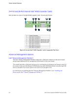
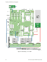
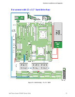
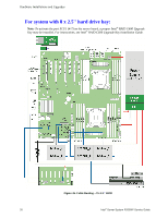
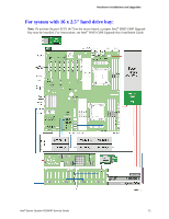
Hardware Installations and Upgrades 2 Hardware Installations and Upgrades Before You Begin Before working with your server product, pay close attention to the "Safety Information" at the beginning of this manual. Note: Whenever you service the system, you must first power down the server and unplug all peripheral devices and the power cord. Tools and Supplies Needed Phillips* (cross head) screwdriver (#2 bit) Needle nosed pliers Anti-static wrist strap and conductive foam pad (recommended) System Reference All references to left, right, front, top, and bottom assume the reader is facing the front of the chassis as it would be positioned for normal operation. Note: The Intel® Server System R2216IP is shown for illlustration purposes, server components with the product family are identical. Cable Routing When you add or remove components from your server system, make sure your cables are routed correctly before reinstalling the server system cover. Use caution to make sure no cables or wires are pinched and that the airflow from the fans is not blocked. Use the figures below to determine the correct cable routing. Note: Red lines are for power connection, dot lines are for optional device connection. For system with 8 x 3.5'' hard drive bay: Note: To activate the port SCU1 (4-7) on the server board, a proper Intel® RAID C600 Upgrade Key must be installed. For instructions, see Intel® RAID C600 Upgrade Key Installation Guide. Intel® Server System R2000IP Service Guide 17
-
 1
1 -
2
-
3
-
4
-
5
-
6
-
7
-
8
-
9
-
10
-
11
-
12
-
13
-
14
-
15
-
16
-
17
-
18
-
19
-
20
-
21
-
22
-
23
-
 24
24 -
 25
25 -
 26
26 -
 27
27 -
 28
28 -
 29
29 -
 30
30 -
 31
31 -
 32
32 -
 33
33 -
 34
34 -
35
-
36
-
37
-
38
-
39
-
40
-
41
-
42
-
43
-
44
-
45
-
46
-
47
-
48
-
49
-
50
-
51
-
52
-
53
-
54
-
55
-
56
-
57
-
58
-
59
-
60
-
61
-
62
-
63
-
64
-
65
-
66
-
67
-
68
-
69
-
70
-
71
-
72
-
73
-
74
-
75
-
76
-
77
-
78
-
79
-
80
-
81
-
82
-
83
-
84
-
85
-
86
-
87
-
88
-
89
-
90
-
91
-
92
-
93
-
94
-
95
-
96
-
97
-
98
-
99
-
100
-
101
-
102
-
103
-
104
-
105
-
106
-
107
-
108
-
109
-
110
-
111
-
112
-
113
-
114
-
115
-
116
-
117
-
118
-
119
-
120
-
121
-
122
-
123
-
124
-
125
-
126
-
127
-
128
-
129
-
130
-
131
-
132
-
133
-
134
-
135
-
136
-
137
-
138
-
139
-
140
-
141
-
142
-
143
-
144
-
145
-
146
-
147
-
148
-
149
-
150
-
151
-
152
-
153
-
154
-
155
-
156
-
157
-
158
-
159
-
160
-
161
-
162
-
163
-
164
-
165
-
166
-
167
-
168
-
169
-
170
-
171
-
172
-
173
-
174
-
175
-
176
-
177
-
178
-
179
-
180
-
181
-
182
-
183
-
184
-
185
-
186
-
187
-
188
-
189
-
190
-
191
-
192
 |
 |
