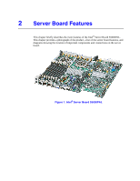
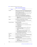
Intel S5000PALR User Guide - Page 17
List of s - s5000pal memory
 |
UPC - 890552612895
View all Intel S5000PALR manuals
Add to My Manuals
Save this manual to your list of manuals |
Page 17 highlights
List of Figures Figure 1. Intel® Server Board S5000PAL 1 Figure 2. Server Board Connector and Component Locations 4 Figure 3. BIOS Select Jumper 5 Figure 4. Recovery Jumpers ...6 Figure 5. Light Guided Diagnostic LEDs 7 Figure 6. Back Panel Connectors 8 Figure 7. DIMM Configuration Diagram 11 Figure 8. Four DIMM Configuration Example 12 Figure 9. Clear Password Jumper 19 Figure 10. Clear CMOS Jumper 20 Figure 11. Installing the Memory 22 Figure 12. ILifting the Processor Socket Handle 24 Figure 13. Installing the Processor 24 Figure 14. Removing the Socket Cover 25 Figure 15. Installing the Heat Sink 26 Figure 16. Replacing the Backup Battery 29 Figure 17. Diagnostic LED Placement Diagram 54 Intel® Server Board S5000PAL User's Guide xvii
-
 1
1 -
2
-
3
-
4
-
5
-
6
-
7
-
8
-
9
-
10
-
11
-
 12
12 -
 13
13 -
 14
14 -
 15
15 -
 16
16 -
 17
17 -
 18
18 -
 19
19 -
 20
20 -
 21
21 -
 22
22 -
23
-
24
-
25
-
26
-
27
-
28
-
29
-
30
-
31
-
32
-
33
-
34
-
35
-
36
-
37
-
38
-
39
-
40
-
41
-
42
-
43
-
44
-
45
-
46
-
47
-
48
-
49
-
50
-
51
-
52
-
53
-
54
-
55
-
56
-
57
-
58
-
59
-
60
-
61
-
62
-
63
-
64
-
65
-
66
-
67
-
68
-
69
-
70
-
71
-
72
-
73
-
74
-
75
-
76
-
77
-
78
-
79
-
80
 |
 |

Intel
®
Server Board S5000PAL User’s Guide
xvii
List of Figures
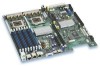
Figure 1. Intel
®
Server Board S5000PAL
..................................................................................
1
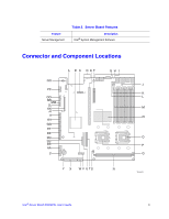
Figure 2. Server Board Connector and Component Locations
.................................................
4
Figure 3. BIOS Select Jumper
...................................................................................................
5
Figure 4. Recovery Jumpers
.....................................................................................................
6
Figure 5. Light Guided Diagnostic LEDs
...................................................................................
7
Figure 6. Back Panel Connectors
..............................................................................................
8
Figure 7. DIMM Configuration Diagram
...................................................................................
11
Figure 8. Four DIMM Configuration Example
..........................................................................
12
Figure 9. Clear Password Jumper
...........................................................................................
19
Figure 10. Clear CMOS Jumper
..............................................................................................
20
Figure 11. Installing the Memory
.............................................................................................
22
Figure 12. ILifting the Processor Socket Handle
.....................................................................
24
Figure 13. Installing the Processor
..........................................................................................
24
Figure 14. Removing the Socket Cover
..................................................................................
25
Figure 15. Installing the Heat Sink
..........................................................................................
26
Figure 16. Replacing the Backup Battery
................................................................................
29
Figure 17. Diagnostic LED Placement Diagram
......................................................................
54