Intel S5500BC Quick Start Guide - Page 1
Intel S5500BC - Server Board Motherboard Manual
 |
UPC - 735858208109
View all Intel S5500BC manuals
Add to My Manuals
Save this manual to your list of manuals |
Page 1 highlights
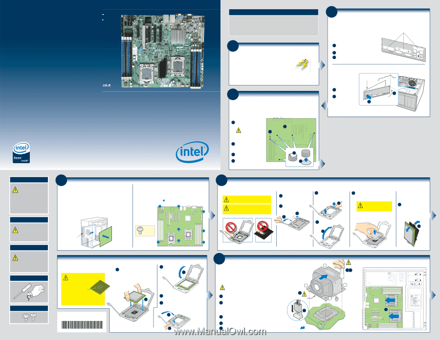
Intel® Server Board S5500BC Quick Start User's Guide Thank you for buying the Intel® Server Board S5500BC. The following information will help you integrate your new server board into a server chassis. The Intel® Server Board S5500BC is designed for use with the Intel® Server Chassis SC5650. For details on these chassis or to select a third party chassis, please visit http://www.intel.com/go/serverbuilder and http://support.intel.com/support/motherboards/server. When installing the server board into a reference chassis, refer to the reference chassis instructions. User Guides are also available on the Intel® Server Deployment Toolkit 3.0 CD that accompanied your Intel® Server Board S5500BC. If you are not familiar with ESD (Electrostatic Discharge) procedures used during system integration, please see the Intel® Server Board S5500BC User's Guide, available on the Intel® Server Deployment Toolkit 3.0 CD or at http://support.intel.com/motherboards/server/s5500BC. Please boot to the Intel® Server Deployment Toolkit 3.0 CD first for BIOS and firmware configuration and updates. Read all cautions and warnings first before starting your server system integration. Warning Read all caution and safety statements in this document before performing any of the instructions. Also see the Intel® Server Board and Server Chassis Safety Information document at: http://support.intel.com/support/ motherboards/server/sb/cs-010770 .htm for complete safety information. Warning Installation and service of this product should only be performed by qualified service personnel to avoid risk of injury from electrical shock or energy hazard. Caution Observe normal ESD [Electrostatic Discharge] procedures during system integration to avoid possible damage to server board and/or other components. Tools Required Phillips* screwdriver Anti-static wrist strap Fastener Identification Guide Intel is a registered trademark of Intel Corporation or its subsidiaries in the United States and other countries. *Other names and brands may be claimed as the property of others. Copyright © 2008, Intel Corporation. All rights reserved. 4 Install the Server Board IMPORTANT NOTE: If you are using a non-Intel server chassis, see your chassis documentation for preparatory steps prior to server board installation. A. Insert the Server Board Place the board into the chassis, making sure that back panel I/O openings and chassis standoffs align correctly. • When using the Intel® Server Chassis SC5650, insert the front of the board first, then slide the board back so the I/O connectors fit through the I/O openings at the rear of the chassis. Intel® Server Chassis SC5650 Shown I/O Openings Front of Board B. Attach the Server Board The directions below are for the Intel® Server Chassis SC5650. For a non-Intel server chassis, use the fasteners that came with your chassis. Use screws to attach the board to the chassis at the 8 locations indicated by the solid blue arrows in the figure [ ]. Intel® Server Chassis SC5650 Intel Server Chassis Fastener Install the Processor(s) continued E. Install the Processor CAUTION: The underside of the processor has components that may damage the socket wires if installed improperly. A Orient the processor with the socket so that the processor cutouts match the two socket pins. Install the processor as shown. Components Processor must align correctly with the socket opening before installation. A DO NOT DROP processor into socket! E52682-004 F. Close Load Plate and Socket Lever A Close the load plate all the way as shown. A B With your finger, push down on the load plate as shown. C Close the socket lever and ensure that the load plate tab engages under the socket lever when fully closed. C B Minimum Hardware Requirements To avoid integration difficulties and possible board damage, your system must meet the following minimum requirements: • Processor: Intel® Xeon® Processor 5500 Series with compatible heat sink. • Memory Type: Minimum of one 1 GB, 240-pin DDR3 800/1066/1333 MT/s RDIMM or UDIMM. • Power: Minimum of 400 W with 3A of standby current, which meets the SSI EPS 5V specification. 1 Preparing the Chassis If using a non-Intel server chassis, refer to the documentation that came with your chassis for preparatory steps. Observe normal ESD (ElectroStatic Discharge) procedures. Place your Intel® Server Chassis and Intel® Server Board on a flat anti-static surface to perform the following integration procedures. Always touch the chassis frame first, before reaching inside to install the server board, make server board connections or install other components. 3 Install Server Board Bumpers IMPORTANT NOTE: If you are using a non-Intel server chassis, see your chassis documentation for preparatory steps prior to server board installation. If you are using an Intel® Server Chassis, use the bumpers that came with the chassis. Prepare Server Board A Rotate board to show underside and hold upright as shown. CAUTION: To avoid B damage to the board, do not lay flat with the component side down. B Locate the five circles as shown. Attach the Bumpers C Remove the backing from each bumper. D Press a bumper onto each of the five circles. A C D 2 Installing the I/O Shield and Attach I/O Labels Note: The I/O shield and label installation procedures shown below apply to the Intel® Server Chassis SC5650. Attach the Labels to the I/O Shield (optional) Labels on outside face of I/O shield Note: Make sure you install the labels on the correct side of the I/O shield. Note the orientation of the cutouts in the drawing before attaching your labels. A Remove the backing from one of the three I/O shield labels included with your server board. ID B Press the label onto the I/O shield as shown. MSB Bit6 Bit5 Bit4 Bit3 Bit2 Bit1 LSB NIC1 NIC2 C Repeat steps to install the second and third I/O shield labels. Install the I/O shield Shield installs from inside of chassis. The labels should be visible from the outside of the chassis. Chassis Back Panel Opening A Insert one side edge of shield as shown. B Push shield firmly into chassis opening until it clicks into place. A Intel® Server Chassis SC5650 shown B 5 Install the Processor(s) Cautions: 1. When opening a socket, DO NOT TOUCH the gold socket wires. 2. When unpacking a processor, hold by the edges only to avoid touching the gold contact wires. A. Open the Socket Lever A Push the lever handle down and away from the socket to release it. B Rotate the lever open all the way. A B B. Open the Load Plate A Push the rear tab with your finger tip to bring the front end of the load plate up slightly. A C. Remove Socket Protective Cover A Grasp the socket protective cover by the two tabs and carefully lift straight up as shown. D. Remove the Processor Protective Cover 1. To avoid damage, DO NOT DROP the cover onto the socket wires or components. A Take the processor out of the box and remove the protective shipping cover. Save the protective cover. B Open the load plate as shown. A B 6 Install Active Heat Sink(s) An active heat sink is required for the Intel® Server Chassis SC5650 DP and BRP. A typical active heat sink is shown below. For a non-Intel chassis, see the documentation accompanying your chassis. CAUTION: The heat sink has thermal interface material (TIM) on the underside of it. Use caution so that you do not damage the thermal interface material. Use gloves to avoid sharp edges. A If a protective film covers the thermal interface material (TIM) on the underside of the heatsink, remove the protective film. B Align heatsink fins to the front and back of the chassis for correct airflow. Airflow goes from front-to-back of chassis. See airflow diagram at right. Each heatsink has four captive fasteners and should be tightened as follows: C Using a #2 Phillips* screwdriver, finger-tighten each fastener diagonally, according to the white-circled numbers. D Securely re-tighten each fastener again in the same order as performed in Step C. E Attach fan power cable to server board as shown. Note: Heatsink styles may vary 2 A TIM E Chassis Front 3 Air Flow 4 CAUTION: Do not over-tighten fasteners. CD 1 Intel® Server Chassis SC5650 Airflow Diagram LOCK Airflow B Airflow
-
 1
1
 |
 |