Intel SASWT4I Hardware User Guide - Page 22
Technical Specifications, LEDs, Table 2. Specifications - raid
 |
View all Intel SASWT4I manuals
Add to My Manuals
Save this manual to your list of manuals |
Page 22 highlights
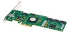
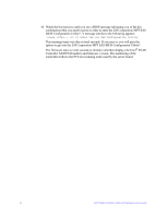
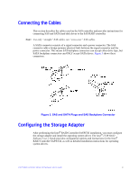
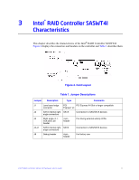
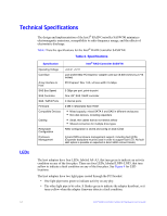
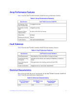
Technical Specifications The design and implementation of the Intel® RAID Controller SASWT4I minimizes electromagnetic emissions, susceptibility to radio frequency energy, and the effects of electrostatic discharge. Table 2 lists the specifications for the Intel® RAID Controller SASWT4I. Table 2. Specifications Specification Operating Voltage Card Size Array Interface to Host SAS Bus Speed SAS Controller SAS / SATA Ports Firmware Compatible Devices Cabling Redundant Configuration Enclosure Management Intel® RAID Controller SASWT4I +3.3 V, +12 V Low-profile MD2 PCI Express* adapter card size (6.600 inches by 2.713 inches) PCI Express* Rev 1.0A, x4 lane width 2.5 Gbps 3 GBps per port, point-to-point One LSI* SAS 1064E controller 4 internal ports 2 MB in reflashable flash ROM • Mixed capacity, mixed SATA II and SAS in different enclosures • Non-disk devices, including expanders • Small, thin cables that do not restrict airflow • Shared connectors for multiple drive types RAID configuration is stored and config on disk (COD) In-band SES enclosure management support, including fault LEDs (Expander backplane must be used in order to support fault LED. No fault LED option is possible or expected in direct HDD connect mode). LEDs The host adapters have four LEDs, labeled A0-A3, that turn green to indicate an activity condition on any of the four phys. There are four LEDs, labeled LNP0-LNP3, that turn yellow to indicate a fault condition on any of the four phys. See Figure 4 for LED locations. The host adapters have two light pipes routed through the PCI bracket: • One light pipe turns green to indicate activity on any phy. • The other light pipe is bi-color. It flashes green to indicate the adapter heartbeat, or it turns yellow when the adapter firmware detects a fault condition. 12 Intel® RAID Controller SASWT4I Hardware User's Guide
-
 1
1 -
2
-
3
-
4
-
5
-
6
-
7
-
8
-
9
-
10
-
11
-
12
-
13
-
14
-
15
-
16
-
 17
17 -
 18
18 -
 19
19 -
 20
20 -
 21
21 -
 22
22 -
 23
23 -
 24
24 -
 25
25 -
 26
26
 |
 |