Intel SE7501CW2 Quick Start Guide - Page 1
Intel SE7501CW2 - E7501 DUAL PGA604 XEON 533MHZ Manual
 |
UPC - 735858160308
View all Intel SE7501CW2 manuals
Add to My Manuals
Save this manual to your list of manuals |
Page 1 highlights
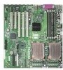
trim scclore/fold Intel®Server Board SE7501CW2 Quick Start User's Guide Start Here Thank you for buying an Intel®Server Board. The following information will help you prepare your server board for integration with your selected server chassis. This guide is for technically qualified persons. Expanded installation instructions and complete product information are available in the Intel®ServerBoard SE7501CW2 Product Guide located on the Resource CD. Minimum Hardware Requirements To avoid integration difficulties and possible board damage, your system must meet the following minimum requirements: • Processor: Minimum of one Intel® Xeon processor with 512KB L2 cache support • Memory: Minimum of one 128 MB, DDR200/266-compliant registered SDRAM 184-pin gold DIMMs. • Power: Minimum of 450W with 2A of standby current, which meets the SSI EPS 12V specification. Additional resources and support for your server board, including supported processors, tested chassis, qualified memory and chassis components, specifications, and software updates, can be found at: hitp://support.inteLcom/supporVmotherboards/server/ SE7501CW2 Build Value With Intel Server Products, Programs and Support Get the high-value server solutions you need by taking advantage of the outstanding value Intel provides to system integrators: • High-quality server building blocks • Extensive breadth of server building blocks • Solutions and tools to enable e-Business • Comprehensive training services1 • Worldwide 24x7 technical support [AT&T Country Code + 866-655-6565]1 • World-class service, including a three-year warranty and Advanced Warranty Replacementl For more information on Intel's added-value server offerings, visit the Intel® ServerBuilder website at: www.intel.com/golserverbuilder Intel ServerBuilder is your one-stop shop for information about all of Intel's Server Building Blocks such as: • Product information including product briefs and technical product specifications • Sales tools such as videos and presentations • Configuration tools to help you build complete solutions • Training information such as the Intel® Online Learning Center • Support information and much more 1Available only to Intel® Channel Program Members, part of Intel® e-Business Network. Before you begin You will need the following tools and equipment: Needle-nosed pliars Flat blade screw driver Phillips* screw driver Antistatic wrist strap • A Attaching the Gasket to the I/O Shield Remove the backing strips from gasket. Press the gasket onto the inside face of the I/O shield as shown. Attaching the Label to theI/O Shield O, 'p Installing the I/O Shield a - Insert one side edge of shield as shown. 0utside face ofI/O shield Remove the backing from the label included with your server board. Press the label onto the outside face of the I/O shield. Chassis Back Panel Push shield firmly into chassis opening until it clicks into place. Shield installs from inside of chassis. The labelshouldbe visible from the outside of the chassis. Fastener Identification Guide (Fasteners are included with chassis O and boxed processor) DIMM 1A Socket DIMM 1B Socket DIMM 2A Socket DIMM 2B Socket CPU1 Socket CPU2 Socket _I 1_ 0 0 Installing the Chassis Standoffs Standoffs are included with your chassis. Standoff numbering varies by chassis. Standoff locations for the Intel Server Chassis SC5200 and SC5250-E are shown below. If you are using a non-Intel chassis, you may need to install the adhesive-backed standoff included with your server board. This standoff is used when the non-Intel chassis does not include a standoff hole in one of the referenced locations. Refer to documentation provided by your chassis vendor for standoff placement information. For the Intel® SC5200 chassis: Install standoffs in positions 7, 18, 19, S and in the eight positions marked P Front of chassis .1 4 67 P 20e • P P P P • P 12 • 23 6 19 • 26 For the Intel® SC5250-E chassis: Install standoffs in positions L, H, C, E, the four positions marked P1, and the four positions marked P2. Front of chassis .K F • A •L P1 • F.1 N e P1 • P1 P• 2 P2 P• 2 P2 I 11 • C Installing the Processor[s] Notes and Cautions: 1. If only ONE processor is to be used, it must be installed in the processor socket labeled CPU1, located closest to the corner of the server board. in2. If installing a SECOND processor, verify that the processors are identical, same voltage and speed. Do notmixprocessors of different types or frequencies. 3. When unpacking a processor, hold by the edges only to avoid touching the pins. 8 4. This server board has "zero-insertion force" sockets. If processor does not drop easily into socket holes, make sure lever is in the full-open position and the processor is oriented properly. 5. Use the retention mechanism clips that come with your boxed processor. The Intel® XeonlM processors 400 MHz and the Intel® XeonTM processors 533 MHz use slightly different clips. Use only the clips that come with your processor. IO Close the Socket Lever IQi Install the Retention Mechanism SC5200: use fasteners provided with boxed processor. SC5250-E: use slightly shorter fasteners provided with chassis. I A Open the Socket Lever Open the lever all the way as shown. Lever Processor Socket IO Install the Processor Align corner mark on the processor to the socket as shown. Retention Mechanism 0 Processor Socket 113 Apply Thermal Grease Apply thermal grease to the top of processor. a WARNING: Installation and service of this product to be performed only by qualified service personnel to avoid risk of injury from electrical shock or energy hazard. the Intel Server Board SE7501CW2 Product e located on the CD that came with your server d for product safety and EMC regulatory pliance information. If you are not familiar with ESD (Electro-Static Discharge) procedures to be used during system assembly, complete ESD Procedures are described in your Intel Server Board SE7501CW2 Product Guide. 112 Installing the Heat Sink and Retention Clips A Retention Clip O Place heat sink onto processor. Heat sink styles may differ. If your heat sink has a flat edge (as shown), the flat edge must face the back of the chassis. ® Tab at inside of retention clip engages slot on heat sink during installation. Side Plastic Tab The center slot in the clip provides room for side-to-side motion while you engage the retention clip tabs. Side Tab Position clip as shown. IN Make sure tabeabove engages slot in heat sink base. Center Tab \ vr, sti Press downward on retention clip end to engage side plastic tab. n Slide clip in direction shown. Note location of centerplastic tab. Snap other end as shown. Repeat steps 1 - 4 for clip at other side of heat sink. L3- 1Installing the Server Board Note: The SC5200 Base and Base Redundant Power Chassis and the SC5250-E Chassis use different fasteners to attach the server board to the chassis. Be sure to use the fastener indicated for your chassis. Fasteners --- are included with your chassis. SC5200 fastener Place the board into the chassis, making sure that the back panel I/O shield openings and the 0 chassis standoffs align correctly. When using the SC5200 chassis, insert the I/O connector side (back) of the board first. When using the SC5250-E chassis, insert the front of the board first, then slide the board back so the VO connectors fit through 0 the I/O shield. Attach the board with the screws at the 10 locations marked in the figure. SC5250-E fastener 141Installing Memory DIMM Memory Modules Notes and Cautions: A single DIMM can be used in the first slot of Bank 1. Bank 1 must be fully populated before populating Bank 2. Memory in Bank 2 must be populated in pairs. See the illustration at the center of this page. 0 The DIMM size, speed and vendor must be the same within a bank. However, the DIMM size can vary between banks. For example, Bank 1 can use two 128 MB DIMMs and Bank 2 can use two 256 MB DIMMs. See "Minimum Hardware Requirements" in the Start Here box above left for correct DIMM specifications. 8 Avoid touching gold contacts when handling or installing DIMMs. 0 0 0 0 O 0 Open both DIMM socket levers. coInsertDIMMmaking sure the connector edge of the DIMM aligns correctly with the slot 0 Check that socket levers are securely latched. 0 0 O Go to SIDE 2 Information in this document is provided in connection with Intel products. No license, express or implied, by estoppel or otherwise, to any intellectual property rights is granted by this document. Except as provided in Intel's Terms and Conditions of Sale for such products, Intel assumes no liability whatsoever, and Intel disclaims any express or implied warranty, relating to sale and/or use of Intel products including liability or warranties relating to fitness fora particular purpose, merchantability, or infringement of any patent, copyright or other intellectual property right. Intel products are not intended for use in medical, life saving, or life sustaining applications. Intel may make changes to specifications and product descriptions at any time, without notice. Intel and Intel Xeon are trademarks or registered trademarks of Intel Corporation or its subsidiaries in the United States and other countries. *0ther names and brands may be claimed as the property of others. Copyright 2003, Intel Corporation. All rights reserved. C29939-002 IIIIIII IIIIVIII VIII NEN ling
-
 1
1
 |
 |
