Intel SR1435VP2 Quick Start Guide - Page 1
Intel SR1435VP2 - Server Platform - 0 MB RAM Manual
 |
UPC - 735858176927
View all Intel SR1435VP2 manuals
Add to My Manuals
Save this manual to your list of manuals |
Page 1 highlights
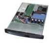
intelo Intel® Server Platform SR1435VP Quick Start User's Guide Thank you for buying an Intel® Server Platform. The following information will help you assemble your Intel® Server Platform and install components. This guide and other supporting documents are located on the web at http://support. Intel .com/support/motherboards/server/SR1435VP2/ • If you are not familiar with ESD (Electrostatic Discharge) procedures used during system integration, please see the Intel® Server Board SE7320P2 User Guide, available at http://support.intel.com/support/motherboards/server/SR1435VP2/ Minimum Hardware Requirements To avoid integration difficulties, make sure you have components from each category below: • Riser Options: • Full Height PCI-Express Riser Connector • Full Height PCI-X Riser Connector • Low-profile PCI-X Riser Connector • Processor: Minimum of one Intel® XeonTM processor at least 2.8 MHz with an 800 MHz FSB with 1U heatsink. • Memory Type: Minimum of one 256MB, DDR266/333 compliant registered SDRAM 184-pin DIMM. • Power: Minimum of 450W with 1.2A of standby current, which meets the SSI EPS 120V specification. Remove the Top Cover 0 Remove the shipping screw. O Depress the latch. 0 Slide the top cover toward the rear and lift upward. Remove Processor Air Duct and Air Baffle O Processor air duct lifts straight up. • O Disengage air baffle from three standoffs on chassis floor and lift straight up. acl Warning Read all caution and safety statements in this document before performing any of the instructions. Also see the Intel® ServerBoardandServer Chassis SafetyInformation document at: http://support.intel.com/support/motherboards/server/sb/cs-010770.htm for complete safety information. Warning A Installation and service of this product to be performed only by qualified service personnel to 4 avoid risk of injury from electrical shock or energy hazard. Caution ...I Af Observe normal ESD [Electrostatic Discharge] • procedures during system integration to avoid possible damage to server board and/or other components. Tools Required Phillips* screwdriver Anti-static wrist strap Fastener Identification Guide Remove the PCI Riser Bracket Lever O Pull both release levers toward center of bracket. O Lift straight up. -4- Lever e Install Memory DIMMs Memory Type: Minimum of one 256MB, DDR266/333 compliant registered SDRAM 184-pin DIMM. Notes and Cautions: Bank 1 (DIMM1B and DIMM1A) must be fully populated before populating Bank 2 (DIMM2B and DIMM2A). Memory must be populated in pairs, except O when using a single DIMM in Bank 1. The DIMM size, speed and vendor must be the same within a bank. However, the DIMM size can vary between banks. For example, Bank 1 can use two 256 MB DIMMs and Bank 2 can use two 512 MB DIMMs. O Note: Foradditionalmemory configurations, see the User Guide for the Intel® ServerBoardSE7320VP2 Bank 2 DIMM 2A Socket DIMM 2B Socket Bank 3 - DIMM 3A Socket -Bank 1 DIMM 1A Socket 0 DIMM 3B Socket DIMM 1B Socket O 00 00 O O Open both DIMM socket levers. O Note location of alignment notch. O Insert DIMM making sure the connector edge of the DIMM aligns correctly with the slot. O Check that socket levers are securely latched. A Avoid touching gold contacts when handling or installing DIMMs. Install PCI Riser Connector (optional) If you do not intend to install an add-in card, skip this procedure and go to Step 8. Depending upon your system configuration, you must install the PCI riser connector(s) that match your add-in card(s). Fullheightriser connectors installon the left, andlow-profile riser connectors installon therightside ofthePCIbracket. le Riser 0 Press and hold the blue PCI riser locking lever. Lo Place riser connector onto retention Height Riser 0 pins, then slide riser connector Eull to the right to lock. i) Release blue lever. Retention Pin Blue Sh Locking Lever Install the Processor(s) and Heatsink(s) Notes and Cautions: A 1. If only ONE processor is to be used, it must be installed in the Processor Socket 1 (CPU1). 2. Do not mix processors of different types or frequencies. 3. When unpacking a processor, hold by the edges only to avoid touching the pins. 4. This server board has "zero-insertion force" sockets. If processor does not drop easily into socket holes, make sure lever is in the full-open position and verify none of the processor pins is bent.. 5. The heat sink has thermal interface material on the underside of it. Use caution so that you do not damage the thermal interface material. A. Open the Socket Lever Open the lever all the way as shown. D. Install the Heat Sink Each heat sink has four captive fasteners and should be tightened using the following procedure: Dl. Finger-tighten each fastener diagonally, according to the numbers below. D2. Securely re-tighten each fastener again in the same order as performed in step Dl. B. Install the Processor Align corner mark on the processor to the socket as shown. A, Do not over-tighten fasteners. 3 1 Note: Heatsink styles may differ. 2 4 . C. Close the Socket Lever 5 0'1° t's*m Note: The ESD Sheet and the Heat Sink Retainer la0 are factory-installed. C.+ Do not remove the Plastic ESD Sheet between the bottom of the server board and the heat sink retainer. at 9 11^("pl C83602-001 Install Add-in Card(s) Open retention clip. 410 Remove filler panel. Insert add-in card until it seats in riser card connector. Left Side Supports, full-height PCI card. Make sure add-in card bracket inserts into slot. Close retention clip. A CAUTION: Observe normal ESD precautions when installing add-in cards. Retention Clip Right Side/ Supports low-profile PCI card only. dr Install PCI Riser Bracket To install the riser bracket assembly: 0 Position riser connectors over the server board riser sockets. 0 Press down uniformly until the four hooks engage the chassis back panel and the riser connectors Riser insert into the Connectors server board sockets. Server Board Sockets 6:4 I 8 Chassis Hooks (4) Back Panel A CAUTION: If you did not install riser connectors for add-in cards, the riser bracket still must be installed to ensure proper system cooling. Rear View of Chassis Back Panel and Riser Bracket Assembly Hooks(4) 0 O Slots (4) Intel is a registered trademark of Intel Corporation or its subsidiaries in the United States and other countries. * Other names and brands may be claimed as the property of others. Copyright 2004, Intel Corporation. All rights reserved. Kemove Hard Drive Carriers lit Carrier'i Latch mt , 0 To remove carrier, locate carrier latch at rear of drive cage and push toward center of drive to release Slide carrier out of chassis. Install Backplane tor Hot Swap Capability Only (optional) If you are not installing a backplane, go to Step 11. If you are installing an optional backplane, go to the backplane kit documentation for instructions on installing the backplane, air baffle and cabling. O oO Complete the backplane installation instructions and then return to this document and go to Step 16 on Side 2.
-
 1
1
 |
 |
