Intel SR1530AHLX Quick Start Guide - Page 1
Intel SR1530AHLX - Server System - 0 MB RAM Manual
 |
UPC - 735858189606
View all Intel SR1530AHLX manuals
Add to My Manuals
Save this manual to your list of manuals |
Page 1 highlights
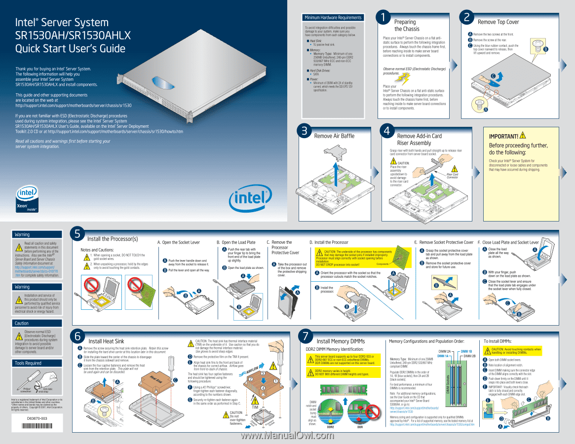
0O Intel® Server System SR1530AH/SR1530AHLX Quick Start User's Guide Thank you for buying an Inter Server System. The following information will help you assemble your Inter Server System SR1530AH/SR1530AHLX and install components. t• O7J This guide and other supporting documents are located on the web at http://support.intel.com/support/motherboards/server/chassis/sr1530 If you are not familiar with ESD (Electrostatic Discharge) procedures Oro used during system integration, please see the Inter Server System SR1530AH/SR1530AHLX User's Guide, available on the Inter Server Deployment Toolkit 2.0 CD or at http://support.intel.com/support/motherboards/server/chassis/sr1530/howto.htm Read all cautions and warnings first before starting your Xeon® Minimum Hardware Requirements To avoid integration difficulties and possible damage to your system, make sure you have components from each category below. • Heat Sink: • 1U passive heat sink. • Memory: Memory Type: Minimum of one 256MB Unbuffered, 240-pin DDR2 533/667 MHz ECC and non-ECC memory DIMM. • HardDisk Drives: • SATA • Power: • Minimum of 350W with 2A of standby current, which meets the SSI EPS 12V specification. Remove Air Baffle Preparing the Chassis Place your Intel® Server Chassis on a flat antistatic surface to perform the following integration procedures. Always touch the chassis frame first, before reaching inside to make server board connections or to install components. Observe normalESD (Electrostatic Discharge) procedures. Place your Intel® Server Chassis on a flat anti-static surface to perform the following integration procedures. Always touch the chassis frame first, before reaching inside to make server board connections or to install components. kW Remove Top Cover Remove the two screws at the front. 0 Remove the screw at the rear. (:0 Using the blue rubber contact, push the top cover rearward to release, then lift upward and remove. A Remove Add-in Card Riser Assembly Grasp riser with both hands and pull straight up to release riser card connector from server board socket. CAUTION: Place the riser assembly upsidedown to avoid damage to the riser card connector. it t i? 11 Riser Card Connector ro,,9 r. IMPORTANT! A Before proceeding further, do the following: Check your Intel® Server System for disconnected or loose cables and components that may have occurred during shipping. ► Warning Read all caution and safety statements in this document before performing any of the instructions. Also see the Intel° ServerBoardandServer Chassis Safety Information document at: http://support.intel.com/support/ motherboards/server/sb/cs-010770 .htm for complete safety information. Warning A Installation and service of this product should only be performed by qualified service personnel to avoid risk of injury from electrical shock or energy hazard. Caution Ir Observe normal ESD [Electrostatic Discharge] procedures during system integration to avoid possible damage to server board and/or other componets. Tools Required Phillips* screwdriver Anti-static wrist strap Intel is a registered trademark of Intel Corporation or its subsidiaries in the United States and other countries. *Other names and brands may be claimed as the property of others. Copyright 2007, Intel Corporation. All rights reserved. D63670-003 Install the Processor(s) Notes and Cautions: /;\ 1. When opening a socket, DO NOT TOUCH the \ gold socket wires. • 2. When unpacking a processor, hold by the edges / \ only to avoid touching the gold contacts. . A. Open the Socket Lever 0 Push the lever handle down and away from the socket to release it. 3 Pull the lever and open all the way. B. Open the Load Plate C. Remove the D. Install the Processor Push the rear tab with your finger tip to bring the front end of the load plate up slightly. 0 Open the load plate as shown. Processor Protective Cover 0 Take the processor out of the box and remove the protective shipping cover. A• CAUTION: The underside of the processor has components that may damage the socket pins if installed improperly. Processor must align correctly with socket opening before installation. DO NOT DROP processor into socket! Components lO Orient the processor with the socket so that the processor cutouts match the socket notches. Install the processor. E. Remove Socket Protective Cover 0 Grasp the socket protective cover tab and pull away from the load plate as shown. 0 Remove the socket protective cover and store for future use. F. Close Load Plate and Socket Lever • Close the load plate all the way as shown. 0 With your finger, push down on the load plate as shown. @ Close the socket lever and ensure that the load plate tab engages under the socket lever when fully closed. VP Install Heat Sink Remove the screw securing the heat sink retention plate. Retain this screw for installing the hard drive carrier at this location later in this document. Slide the plate toward the center of the chassis to disengage it from the chassis sidewall and remove. Loosen the four captive fasteners and remove the heat sink from the retention plate. This plate will not be used again and can be discarded. A CAUTION: The heat sink has thermal interface material (TIM) on the underside of it. Use caution so that you do not damage the thermal interface material. Use gloves to avoid sharp edges. 0 Remove the protective film on the TIM if present. Align heat sink fins to the front and back of the chassis for correct airflow. Airflow goes from front-to-back of chassis. The heat sink has four captive fasteners IR 3 and should be tightened using the following procedure: 2 1 0 Using a #2 Phillips* screwdriver, 4 finger-tighten each fastener diagonally, according to the numbers shown. @ Securely re-tighten each fastener again in the same order as performed in Step C. TIM A CAUTION: . Do not over-tighten fasteners. U Install Memory DIMMs DDR2 DIMM Memory Identification: A This server board supports up to four DDR2-533 or DDR2-667 ECC or non-ECC unbuffered DIMMs. DDR DIMMs are not supported on this server board. ▪ DDR2 memory varies in height. DO NOT MIX different DIMM heights and types. n DIMM notch and socket bump must align as shown. DDR2 DDR Memory Configurations and Population Order: DIMM 2A Memory Type: Minimum of one 256MB Unbuffered, 240-pin DDR2 533/667 MHz compliant DIMM. - DIMM 1B T DIMM 2B DIMM Sockets Populate DDR2 DIMMs in the order of 1A, 1B [blue sockets], then 2A and 2B [black sockets]. For best performance, a minimum of four 0 DIMMs is recommended. Note: For additional memory configurations, see the User Guide on the CD that accompanied your Intel® Server Board S3000AH, or go to: 0 htlp://supportintel.com/supporl/motherboards/ server/chassis/sr1530 Memory sizing and configuration is supported only for qualified DIMMs approved by Intel®. For a list of supported memory, see the tested memory list at htlp://supportintel.com/supporl/motherboards/server/chassis/sr1530/compathtm To Install DIMMs: , CAUTION: Avoid touching contacts when handling or installing DIMMs. O Open both DIMM socket levers. Note location of alignment notch. @ Insert DIMM making sure the connector edge of the DIMM aligns correctly with the slot. 0 Push down firmly on the DIMM until it snaps into place and both levers close. GO IMPORTANT! Visually check that each latch is fully closed and correctly engaged with each DIMM edge slot. /Th
-
 1
1
 |
 |