Intermec PX4i PX4i and PX6i Print Kit Integration Guide
Intermec PX4i Manual
 |
View all Intermec PX4i manuals
Add to My Manuals
Save this manual to your list of manuals |
Intermec PX4i manual content summary:
- Intermec PX4i | PX4i and PX6i Print Kit Integration Guide - Page 1
PX4i | PX6i Print Kit Integration Guide - Intermec PX4i | PX4i and PX6i Print Kit Integration Guide - Page 2
, Smart Mobile Computing, SmartSystems, TE 2000, Trakker Antares, and Vista Powered are either trademarks or registered trademarks of Intermec Technologies Corporation. There are U.S. and foreign patents as well as U.S. and foreign patents pending. ii PX4i and PX6i Print Kit Integration Guide - Intermec PX4i | PX4i and PX6i Print Kit Integration Guide - Page 3
Support v Service Location Support v Who Should Read This Manual vi Related Documents vi About This Integration Guide 9 About the PX4i and PX6i Print Kits 9 About the Print Kit Parts 10 Main Logic Board 10 Power Supply and Driver Board 10 Print Module 11 Keypad and Display Assembly - Intermec PX4i | PX4i and PX6i Print Kit Integration Guide - Page 4
Contents iv PX4i and PX6i Print Kit Integration Guide - Intermec PX4i | PX4i and PX6i Print Kit Integration Guide - Page 5
Contact Us. Service Location Support For the most current listing of service locations, go to www.intermec.com and click Support >Returns and Repairs > Repair Locations. For technical support in South Korea, use the after service locations listed below: PX4i and PX6i Print Kit Integration Guide v - Intermec PX4i | PX4i and PX6i Print Kit Integration Guide - Page 6
for use in a custom print applicator system. Related Documents Here are some related Intermec documents you might find useful: • PX4i and PX6i High Performance Printer User's Manual • Intermec Fingerprint Command Reference Manual • Intermec Fingerprint Developer's Guide The Intermec web site at www - Intermec PX4i | PX4i and PX6i Print Kit Integration Guide - Page 7
Before You Begin If your product does not have its own product page, click Support > Manuals. Use the Product Category field, the Product Family field, and the Product field to help you locate the documentation for your product. PX4i and PX6i Print Kit Integration Guide vii - Intermec PX4i | PX4i and PX6i Print Kit Integration Guide - Page 8
Before You Begin viii PX4i and PX6i Print Kit Integration Guide - Intermec PX4i | PX4i and PX6i Print Kit Integration Guide - Page 9
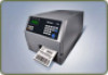
-dpi printhead. • a main logic board for controlling the print hardware and communicating with your controller. • an AC power supply and driver board. Base 2 kits also include a keyboard and 2-line display for printer messages and information. For more information, see "About the Print Kit Parts" on - Intermec PX4i | PX4i and PX6i Print Kit Integration Guide - Page 10
on part version. Power Supply and Driver Board The power supply (P/N 1-971132-9xx) delivers 24 VDC to the driver board. AC power input voltage range is 90 to 265 VAC, 45-65 Hz. Voltage and temperature are monitored and the supply is over-current protected. Power Supply 10 PX4i and PX6i Print Kit - Intermec PX4i | PX4i and PX6i Print Kit Integration Guide - Page 11
by other printer components. This board connects to P2 and P3 on the power supply board. Driver Board Print Module The print module (4-inch: P/N 1-040086-9xx, or 6-inch: P/N 1-040087-9xx) includes a 203-dpi or 300-dpi printhead, a stepper motor that drives the rollers, a tear bar, and a label stop - Intermec PX4i | PX4i and PX6i Print Kit Integration Guide - Page 12
in) Note: You can also order a 400-dpi printhead (P/N 850-812-9xx) to use with the PX4i and PX6i Print Kits. For information, contact your Intermec sales representative. Keypad and Display Assembly The optional keypad and display assembly (P/N 1-040197-xx) includes a self-adhesive membrane switch - Intermec PX4i | PX4i and PX6i Print Kit Integration Guide - Page 13
1 includes hardware for use with thermal transfer ribbon. For more information, see "About the Parts in Option Kit 1" on page 14. • Option Kit 2 includes media supply hub hardware. For more information, see "About the Parts in Option Kit 2" on page 15. PX4i and PX6i Print Kit Integration Guide 13 - Intermec PX4i | PX4i and PX6i Print Kit Integration Guide - Page 14
unit (P/N 1-040189-xx) keeps the ribbon tight to prevent wrinkling and creasing. The adjustable hub fits different ribbon widths. Use two M4 x 8 mm Torx screws (supplied) to mount the ribbon supply unit to your printer chassis. Ribbon Supply Unit 14 PX4i and PX6i Print Kit Integration Guide - Intermec PX4i | PX4i and PX6i Print Kit Integration Guide - Page 15
(supplied) to mount the ribbon rewind unit to your printer chassis. The ribbon rewind unit includes a belt and a tension adjust gear and axle. Ribbon Rewind Unit Ribbon Sensor The ribbon sensor (P/N 1-974005-xx) determines when the ribbon supply is running low, and must be mounted at a specific - Intermec PX4i | PX4i and PX6i Print Kit Integration Guide - Page 16
the media supply hub are mounted on the same chassis panel, the guide plate (P/N 1-040296-xx) keeps the media correctly aligned with the print mechanism. Use three M4 x 8 mm Torx screws (supplied) to mount the guide plate to your printer chassis. Guide Plate 16 PX4i and PX6i Print Kit Integration - Intermec PX4i | PX4i and PX6i Print Kit Integration Guide - Page 17
. Liner Takeup Unit The liner takeup unit (P/N 1-040187-xx) rewinds the spent media liner and is powered by its own stepper motor. Use two M4 x 8 mm Torx screws (supplied) to mount the liner takeup unit to your printer chassis. Liner Takeup Unit PX4i and PX6i Print Kit Integration Guide 17 - Intermec PX4i | PX4i and PX6i Print Kit Integration Guide - Page 18
) uses a pair of belts (supplied) to drive the liner takeup unit and the liner drive roller in the print mechanism. Use four M4 x 8 mm Torx screws (supplied) to install the stepper motor on the motor mount. The motor connects to P11 on the driver board. 18 PX4i and PX6i Print Kit Integration Guide - Intermec PX4i | PX4i and PX6i Print Kit Integration Guide - Page 19
unit and the liner drive roller in the print module. About the Parts in Option Kit 4 Option Kit 4 includes chassis parts that are pre-drilled for use with the PX4i and PX6i Print Kit components. This kit includes center, bottom, and back plates as used in the PX4i and PX6i printers. PX4i and PX6i - Intermec PX4i | PX4i and PX6i Print Kit Integration Guide - Page 20
-xx 524-123-0xx 524-126-0xx Description Bottom plate for 101.6 mm (4 in) printer hardware Bottom plate for 152.4 mm (6 in) printer hardware Center plate Rear plate for 101.6 mm (4 in) printer hardware Rear plate for 152.4 mm (6 in) printer hardware 20 PX4i and PX6i Print Kit Integration Guide - Intermec PX4i | PX4i and PX6i Print Kit Integration Guide - Page 21
PX4i and PX6i Print Kit Integration Guide 21 - Intermec PX4i | PX4i and PX6i Print Kit Integration Guide - Page 22
22 PX4i and PX6i Print Kit Integration Guide - Intermec PX4i | PX4i and PX6i Print Kit Integration Guide - Page 23
PX4i and PX6i Print Kit Integration Guide 23 - Intermec PX4i | PX4i and PX6i Print Kit Integration Guide - Page 24
Worldwide Headquarters 6001 36th Avenue West Everett, Washington 98203 U.S.A. tel 425.348.2600 fax 425.355.9551 www.intermec.com © 2011 Intermec Technologies Corporation. All rights reserved. PX4i and PX6i Print Kit Integration Guide *944-633-001* P/N 944-633-001
-
 1
1 -
 2
2 -
 3
3 -
 4
4 -
 5
5 -
 6
6 -
 7
7 -
8
-
9
-
10
-
11
-
12
-
13
-
14
-
15
-
16
-
17
-
18
-
19
-
20
-
21
-
22
-
23
-
24
 |
 |

PX
4i
| PX
6i
Print Kit
Integration Guide