Invacare 5000IVC Owners Manual - Page 27
Inspecting the Bed
 |
View all Invacare 5000IVC manuals
Add to My Manuals
Save this manual to your list of manuals |
Page 27 highlights
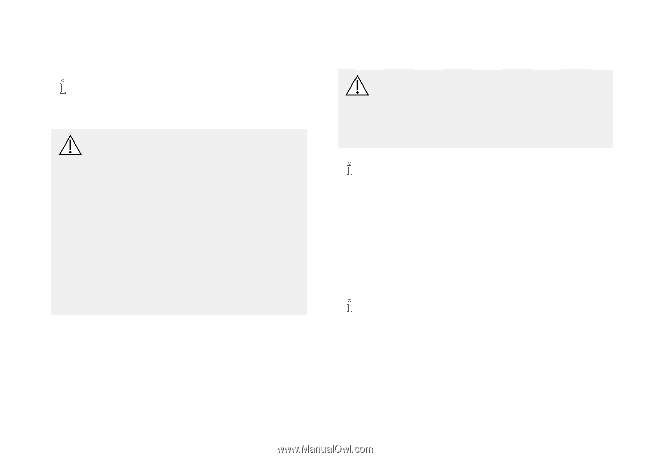
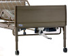
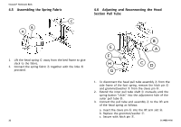
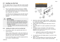
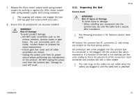
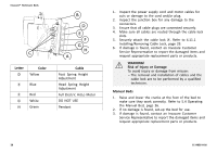
7. Release the Hi/Lo motor output shaft spring-loaded coupler by pushing in against the Hi/Lo motor output shaft spring-loaded coupler and turning clockwise. The coupling will release and engage the foot end top gear box output shaft cross pins. 8. Ensure that all components are securely installed WARNING! Risk Of Damage To avoid product damage: - DO NOT open assemblies such as the motors, pendant, junction boxes or gear boxes. No user serviceable parts are inside. Contact dealer or Invacare for repair/replacement. - Ensure gear box cover and all other assemblies are closed. - Unplug the power cord from its power source before performing any maintenance on the product. DO NOT unplug the power cord from the junction box. Damage to cord will result. Set-up 4.11 Inspecting the Bed Electric Beds WARNING! Risk of Injury or Damage To avoid injury or damage: - When installing any connectors into the junction box, be sure the cable lock is secure after installation. The following procedure is for full/semi-electric beds only. All motors, the junction box B, connectors C and wiring are located on the foot spring section. All connectors will arrive plugged into the junction box. If a connector is not plugged into the junction box when received or if a function of the bed is not working use the color coding to check the placement of the connectors. Each connector and junction box slot is color coded. The color rings on the cables are not visible when the cables are plugged in and the cable lock is attached. 1114836-H-05 27
-
 1
1 -
2
-
3
-
4
-
5
-
6
-
7
-
8
-
9
-
10
-
11
-
12
-
13
-
14
-
15
-
16
-
17
-
18
-
19
-
20
-
21
-
 22
22 -
 23
23 -
 24
24 -
 25
25 -
 26
26 -
 27
27 -
 28
28 -
 29
29 -
 30
30 -
 31
31 -
 32
32 -
33
-
34
-
35
-
36
-
37
-
38
-
39
-
40
-
41
-
42
-
43
-
44
-
45
-
46
-
47
-
48
 |
 |