Invacare 9805 Owners Manual - Page 27
Raising/Lowering Model Hydraulic Lifts, Raising the Lift, - hydraulic lift slings
 |
View all Invacare 9805 manuals
Add to My Manuals
Save this manual to your list of manuals |
Page 27 highlights
DETAIL "A" Shifter Handle Base Closed Base Open SECTION 7-OPERATION Shifter Handle DETAIL "B" Locked Step 1 Step 2 Step 3 FIGURE 7.1 Operating the Patient Lift - Opening the Legs of the Adjustable Base Raising/Lowering Model Hydraulic Lifts NOTE: For this procedure, refer to FIGURE 7.2 on page 28. There are two controls on the pump assembly: 1. The control valve 2. The pump handle Raising the Lift The control valve MUST be in the closed position (control valve positioned towards pump handle) to move the pump handle up and down to elevate the boom and the patient. Part No 1024492 27 Portable Patient Lift and Sling
-
 1
1 -
2
-
3
-
4
-
5
-
6
-
7
-
8
-
9
-
10
-
11
-
12
-
13
-
14
-
15
-
16
-
17
-
18
-
19
-
20
-
21
-
 22
22 -
 23
23 -
 24
24 -
 25
25 -
 26
26 -
 27
27 -
 28
28 -
 29
29 -
 30
30 -
 31
31 -
 32
32 -
33
-
34
-
35
-
36
-
37
-
38
-
39
-
40
-
41
-
42
-
43
-
44
 |
 |
SECTION 7—OPERATION
Part No 1024492
27
Portable Patient Lift and Sling
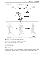
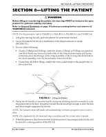
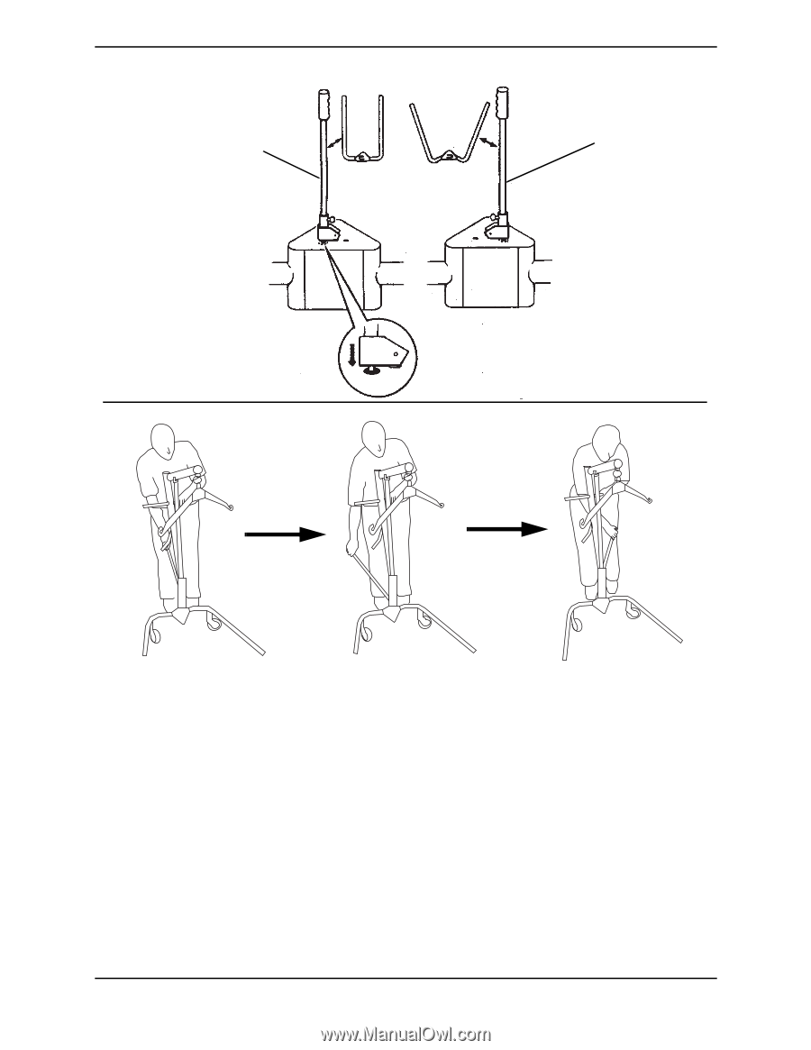
FIGURE 7.1
Operating the Patient Lift - Opening the Legs of the Adjustable Base
Raising/Lowering Model Hydraulic Lifts
NOTE: For this procedure, refer to FIGURE 7.2 on page 28.
There are two controls on the pump assembly:
1.
The control valve
2.
The pump handle
Raising the Lift
The control valve MUST be in the closed position (control valve positioned towards pump
handle) to move the pump handle up and down to elevate the boom and the patient.
Base Closed
Base Open
Shifter
Handle
Shifter
Handle
Locked
DETAIL “B”
DETAIL “A”
Step 1
Step 2
Step 3