Invacare ALR19HBFR Owners Manual - Page 21
Adjusting Wheel Lock
 |
View all Invacare ALR19HBFR manuals
Add to My Manuals
Save this manual to your list of manuals |
Page 21 highlights
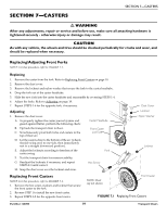
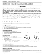
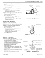
SECTION 8-HAND BRAKES/WHEEL LOCKS 1. Loosen the brake handle adjustment nut by turning clockwise. 2. Perform one of the following: • Loosen brake handle tension ‐ Turn the brake handle nut clockwise. NOTE: If the brake lever is scraping the rear wheel, the brake handle must be loosened. • Tighten brake handle tension ‐ Turn the brake handle nut counterclockwise. NOTE: If the brake lever does not respond quickly, tighten brakes. 3. Turn the brake handle adjustment nut counterclockwise to secure in place. 4. Do one of the following: • Acceptable tension ‐ Repeat STEPS 1 ‐ 3 for the opposite side, if necessary. • Unacceptable tension ‐ Refer to Adjusting Cable Adjuster Unit on page 21. Adjusting Cable Adjuster Unit NOTE: For this procedure, refer to FIGURE 8.3. NOTE: Test the brake with the brake handle. Observe how the brake lever engages the wheel. If the tension of the brake handle is still too loose or too tight, adjust using the following steps: 1. Ensure brake handle is not locked. 2. Do one of the following: • To Loosen: Brace the jam nut while turning the adjustment screw clockwise. • To Tighten: Brace the jam nut while turning the adjustment screw counterclockwise. 3. Repeat with other brake. Brake Handle Nut Brake Handle Adjustment Nut Brake Cable FIGURE 8.2 Adjusting Brake Handle Brake Lever Adjustment Screw Jam Nut FIGURE 8.3 Adjusting Cable Adjuster Unit Adjusting Wheel Lock NOTE: For this procedure, refer to FIGURE 8.4. 1. Loosen the bolt and locknut that secure the wheel lock assembly to the transport chair frame. 2. Adjust the position of wheel lock until the measurement between the rear wheel and the wheel lock shoe is between 5/32 and 5/16‐inches. 3. Securely tighten the bolt and locknut. 4. Engage the wheel lock. 5. Push against the transport chair and determine if the wheel lock engages the wheel lock shoe enough to hold the transport chair. 6. Repeat the above procedures until the wheel lock holds the transport chair. 7. Repeat STEPS 1‐6 for the opposite wheel lock. Locked Position Wheel Lock Shoe 5/32 and 5/16 inches Unlocked Position Wheel Lock Handle Bolt and Locknut Rear Wheel Front of Transport Chair FIGURE 8.4 NOTE: Lightweight Transport wheel lock shown. Adjusting Wheel Lock Part No.1125095 21 Transport Chairs
-
 1
1 -
2
-
3
-
4
-
5
-
6
-
7
-
8
-
9
-
10
-
11
-
12
-
13
-
14
-
15
-
 16
16 -
 17
17 -
 18
18 -
 19
19 -
 20
20 -
 21
21 -
 22
22 -
 23
23 -
 24
24
 |
 |
