JBL VLA901Hi VLA White Paper - Page 6
The Jbl Vla Series Family Of Products
 |
View all JBL VLA901Hi manuals
Add to My Manuals
Save this manual to your list of manuals |
Page 6 highlights
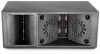
The specially designed pressure plate mounted over the LF transducers serves two purposes. The first is to form part of a smooth transition into the waveguide for the mid-frequency drivers. The second purpose is to equalize the pressure across the low-frequency transducer so that it does not develop a rocking mode thus allowing the transducers to achieve their rated power output capability. This rocking mode can happen when a transducer is mounted in an environment where high pressure differentials are possible, like the inside of a very high power waveguide. So as not to interfere in any way with the mid-frequency energy, the HF waveguide is mounted to the side the low/mid waveguide. This becomes particularly useful for wider patterns where the width of the HF waveguide can begin to obstruct the mid frequency energy. Figure 3: JBL VLA901H - Front View Driver Coupling For the high power versions, proprietary throats were developed to allow two mid-frequency drivers to combine into the same opening allotted to a single driver for the standard versions and four mid-frequency drivers to combine for the "H" versions. The geometry of the rest of the mid-frequency waveguide remains unchanged. A unique summing wave-former has been developed for the JBL2431 series driver that effectively sums two drivers into a common opening. This is another technology borrowed from the JBL PD700 series. Technical details of this may be found in JBL Tech Note Volume 1, Number 29. For the high-output versions of the JBL VLA SERIES, this summing waveguide is combined with the line-array technology of the VerTec to create an extremely high-power high frequency section. The JBL VLA SERIES FAMILY OF PRODUCTS The JBL VLA SERIES is composed of six models. Three horizontal coverage patterns are offered, each horizontal pattern comes in standard and high-powered (H) versions. 5
-
 1
1 -
 2
2 -
 3
3 -
 4
4 -
 5
5 -
 6
6 -
 7
7 -
 8
8 -
 9
9 -
 10
10 -
 11
11 -
 12
12 -
13
-
14
-
15
-
16
-
17
-
18
-
19
-
20
-
21
 |
 |
