JET Tools BDB-1340A User Manual
JET Tools BDB-1340A Manual
 |
View all JET Tools BDB-1340A manuals
Add to My Manuals
Save this manual to your list of manuals |
JET Tools BDB-1340A manual content summary:
- JET Tools BDB-1340A | User Manual - Page 1
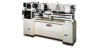
This .pdf document is bookmarked Operation and Maintenance Instructions Belt Drive Bench Lathe, 13x40-inch Model BDB-1340A (shown with optional 321443AK stand) For Parts List and Electrical Diagrams, see document M-321357A JET 427 New Sanford Road LaVergne, Tennessee 37086 Ph.: 800-274-6848 www. - JET Tools BDB-1340A | User Manual - Page 2
Support Please contact Technical Service by calling 1-800-274-6846. Please note that you will be asked to provide proof of initial purchase when calling. If a product requires further inspection, the Technical Service representative will explain and assist with any additional action needed. JET - JET Tools BDB-1340A | User Manual - Page 3
Table of Contents Warranty and Service ...2 Table of Contents ...3 Warning...3 Specifications ...5 Dimensions of optional stand (p/n injury. 3. This manual is intended to familiarize you with the technical aspects of this lathe. It is not, nor was it intended to be, a training manual. 4. This machine - JET Tools BDB-1340A | User Manual - Page 4
tools sharp and clean for the best and safest performance. Follow instructions for lubricating and changing accessories. 25. Turn off the machine and machine. Familiarize yourself with the following safety notices used in this manual: This means that if precautions are not heeded, it may result - JET Tools BDB-1340A | User Manual - Page 5
Specifications Model Number...BDB-1340A Stock Number...321360A Capacities: Swing Over Bed ...13" Swing Over The above specifications were current at the time this manual was published, but because of our policy of continuous improvement, JET reserves the right to change specifications at any time - JET Tools BDB-1340A | User Manual - Page 6
this optional stand for the BDB-1340A Lathe, contact your dealer or call JET customer service. Assembly Contents of the Shipping Container (Figures 1 and 2) 1 Lathe 1 Steady Rest (mounted on lathe) 1 Follow Rest (mounted on lathe) 1 6" Three Jaw Chuck (mounted on lathe) 1 8" Four Jaw Chuck 1 12 - JET Tools BDB-1340A | User Manual - Page 7
Clean-Up 1. Finish removing the wooden crate from around the lathe. 2. Unbolt the lathe from the shipping crate bottom. 3. Choose a location for the lathe that is dry, has good lighting, and has enough room to be able to service the lathe on all four sides. 4. Assemble parts fastened to the crate - JET Tools BDB-1340A | User Manual - Page 8
for chuck preparation! Failure to comply may cause serious injury and/or damage to the lathe! Note: Before removing the chuck from the spindle, place a way board across the bedways under the chuck. 1. Support the chuck while turning three camlocks 1/4 turn counter-clockwise with the chuck key which - JET Tools BDB-1340A | User Manual - Page 9
at all lubrication points and all reservoirs filled to operating level before the lathe is placed into service. Failure to comply may cause serious damage to the lathe. 1. Headstock - Oil must be up to indicator mark in both oil sight glasses (A, Fig. 5). Top off with Mobil DTE® Oil Heavy Medium - JET Tools BDB-1340A | User Manual - Page 10
5. Apron - Oil must be up to indicator mark in oil sight glass (A, Fig. 8). Top off with Mobil DTE® Oil Heavy Medium. Fill by removing oil plug (B, Fig. 8). After the first three months of operation, drain oil completely (drain is on the bottom of the apron) and refill with Mobil DTE® Oil Heavy - JET Tools BDB-1340A | User Manual - Page 11
or damage to the machinery and property. The BDB-1340A bench lathe is rated at 2HP, 1PH, 230V only. Confirm that power available at the lathe's location is the same rating as the lathe. Make sure the lathe is properly grounded. General Description Lathe Bed The lathe bed (A, Fig. 12) is made of high - JET Tools BDB-1340A | User Manual - Page 12
to the gearbox at the left for automatic feed and lead. They are supported by bushings on both ends. Both are equipped with brass shear pins. Gear machine bed. Steady Rest The steady rest (F, Fig. 13) serves as a support for shafts on the free tailstock end. The steady rest is mounted on the - JET Tools BDB-1340A | User Manual - Page 13
lock. Turn counter-clockwise and loosen to unlock. Caution: cross slide lock screw must be unlocked before engaging automatic feeds or damage to the lathe may occur. 10. Carriage Lock (J, Fig. 16) - Turn hex socket cap screw clockwise and tighten to lock. Turn counter-clockwise and loosen to unlock - JET Tools BDB-1340A | User Manual - Page 14
11. Longitudinal Traverse Handwheel (A, Fig. 17) - Rotate handwheel clockwise to move the apron assembly toward the tailstock (right). Rotate the wheel counter-clockwise to move the apron assembly toward the headstock (left). 12. Feed Selector (B, Fig. 17) - Push lever to the left and down to - JET Tools BDB-1340A | User Manual - Page 15
-speed range while back gear (B1) is engaged. Failure to comply may result in gear damage. Adjustments Break-In Procedure During manufacturing and testing, this lathe has been operated in the low R.P.M. range for three hours. To allow time for the gears and bearings to break-in and run smoothly, do - JET Tools BDB-1340A | User Manual - Page 16
Change Gear Replacement Note: The 32T x 127T x 48T gears are installed in the end gear compartment when delivered from the factory. This combination will cover most inch feeds and threads under normal circumstances. The additional gears found in the toolbox are used for some metric threads and feeds - JET Tools BDB-1340A | User Manual - Page 17
Thread and Feed Chart 17 - JET Tools BDB-1340A | User Manual - Page 18
Automatic Feed Operation and Feed Changes 1. Move forward/reverse selector (A, Fig. 25) up or down depending on desired direction. 2. Set the selector handle (B, Fig. 26) to the "P" position and turn knob (C, Fig. 26) counter-clockwise so the arrow is pointing up to start the feed rod rotating. - JET Tools BDB-1340A | User Manual - Page 19
an engineer's precision level on the bedways, make sure the lathe is level side to side and front to back. If the lathe is not level, correct to a level condition before proceeding. . Do not use the tailstock or center to support the other end. 4. Set up and cut along five inches of the bar stock. 19 - JET Tools BDB-1340A | User Manual - Page 20
5. Using a micrometer, measure the bar stock next to the chuck and at the end. The measurement should be the same. 6. If the measurements are not the same and adjustment is required, loosen the four bolts that hold the headstock to the bed. Do not loosen completely; some drag should remain. 7. - JET Tools BDB-1340A | User Manual - Page 21
Parts List and Electrical Diagrams For Lathe models BDB-1340A, GHB-1340A, GHB-1440A (GHB-1340A shown with optional stand 321443AK) For GHB-1340A/1440A Operating Instructions, see document M-321357A-1 For BDB-1340A Operating Instructions, see document M-321360A JET 427 New Sanford Road LaVergne - JET Tools BDB-1340A | User Manual - Page 22
of contents...2 Replacement parts ...3 1.0 BDB-1340A Headstock Assembly I - Exploded View 4 1.1 BDB-1340A Headstock Assembly I - Parts List 5 2.1 BDB-1340A Headstock Assembly II - Exploded View 6 2.2 BDB-1340A Headstock Assembly II - Parts List 7 3.1 BDB-1340A Headstock Assembly III - Exploded - JET Tools BDB-1340A | User Manual - Page 23
Replacement parts To order parts or reach our service department, call 1-800-274-6848 Monday through Friday (see our website for business hours, www.jettools.com). Having the Model Number and Serial Number of your machine available when you call will allow us to serve you quickly and accurately. 3 - JET Tools BDB-1340A | User Manual - Page 24
1.0 BDB-1340A Headstock Assembly I - Exploded View 4 - JET Tools BDB-1340A | User Manual - Page 25
1.1 BDB-1340A Headstock Assembly I - Parts List Index No Part No Description Size Qty 1 ...1 84A............04723A Cover Hinge 1 84B............04723B End Cover Hinge 1 85 04705 Strut ...1 86 BDB1340A-02118A... Arm ...1 87 TS-1523031 Set Screw M6 x 10 2 88 04725B Plunger ...1 89 - JET Tools BDB-1340A | User Manual - Page 26
2.1 BDB-1340A Headstock Assembly II - Exploded View 6 - JET Tools BDB-1340A | User Manual - Page 27
2.2 BDB-1340A Headstock Assembly II - Parts List Index No Part No Description Size Qty 2 TS-1503051 Socket Set Screw M8 x 10 4 3 BB-30212 Taper Roller Bearing 60 x - JET Tools BDB-1340A | User Manual - Page 28
3.1 BDB-1340A Headstock Assembly III - Exploded View 8 - JET Tools BDB-1340A | User Manual - Page 29
3.2 BDB-1340A Headstock Assembly III - Parts List Index No Part No Description Size Arm ...1 76 TS-1503051 Hex Socket Cap Screw M6 x 20 2 77 BB-6204 Ball Bearing 6204 1 78 BDB1340A-04108 ..... Pulley ...1 80 04711 Shaft ...1 82 04710 Spacer ...1 126 TS-1523011 Set Screw M6 x 6 1 - JET Tools BDB-1340A | User Manual - Page 30
4.1 GHB-1340A/1440A Headstock Assembly I - Exploded View 10 - JET Tools BDB-1340A | User Manual - Page 31
65 GHB1340A-04248-1.. Handle ...1 66 GHB1340A-04249..... Handle ...1 68 04402 Shift Fork ...1 69 04403 Shift Fork ...1 78 GHB1340-4506 ......... Gasket (GHB-1340A only 1 GHB1440A-02507..... Gasket (GHB-1440A only 1 87 TS-1503051 Hex Socket Cap Screw M6 x 20 4 88 TS-1503061 Hex Socket - JET Tools BDB-1340A | User Manual - Page 32
No Description Size Qty 157 GHB1340A-02502..... Rubber Mat (GHB-1340A only 1 GHB1440A-02503..... Rubber Mat (GHB-1440A only 1 16 4 GHB1340A-160......... Oil Sight Glass (not shown) (GHB-1340A serial #10052363A and lower).......... 1 GHB1340A-160M...... Oil Sight Glass (not shown M27x1.5 - JET Tools BDB-1340A | User Manual - Page 33
5.1 GHB-1340A/1440A Headstock Assembly II - Exploded View 13 - JET Tools BDB-1340A | User Manual - Page 34
5.2 GHB-1340A/1440A Headstock Assembly II - Parts List Index No Part No Description Size Qty 4 04104Z Rear Cover ...1 5 04105 Pulley ...1 6 GHB1340-4106 ......... Plug...1 25 04209 Gear 2m43T 1 - JET Tools BDB-1340A | User Manual - Page 35
6.1 GHB-1340A/1440A Headstock Assembly III - Exploded View 15 - JET Tools BDB-1340A | User Manual - Page 36
6.2 GHB-1340A/1440A Headstock Assembly III - Parts List Index No Part No Description Size Qty 1 GHB1340A-02103..... Collar 1-1/4" I.D. C'bore .......... 1 GHB1340A-02103N .. Collar 1-3/8" I.D. C'bore .......... 1 2 04102 Collar (serial #07061677A - JET Tools BDB-1340A | User Manual - Page 37
7.1 Bed Assembly I - Exploded View 17 - JET Tools BDB-1340A | User Manual - Page 38
32A1106 Collar ...1 16 GHB1340A-1701....... Lead Screw GHB-1340A 1 BDB1340A-1701 ....... Lead Screw BDB-1340A 1 17 321728 Key...1 18 321706 Collar ...1 19 GHB1340A-1702....... Feed Rod GHB-1340A 1 BDB1340A-1702 ....... Feed Rod BDB-1340A 1 20 01707 Brake Ring ...1 21 GHB1340A-21B - JET Tools BDB-1340A | User Manual - Page 39
Size Qty 69 GHB1340-69B........... Pin 8 x 60 2 70 GHB1340A-74B ........ Set Screw M12 x 40 1 71 TS-1504071 Hex Socket Cap Screw M8 x 35 (BDB 2 TS-1504081 Hex Socket Cap Screw M8 x 40 (GHB 2 72 TS-1551061 Lock Washer M8 4 73 TS-1551071 Lock Washer M10 4 74 TS-1550061 Washer - JET Tools BDB-1340A | User Manual - Page 40
8.1 Bed Assembly II - Exploded View 20 - JET Tools BDB-1340A | User Manual - Page 41
1 C0632-01727 Oil Plate GHB-1440A 1 BDB1340A-01701B... Oil Plate (serial #1204B1274A and lower BDB-1340A 1 BDB1340A-01701BJ . Oil Plate (serial #1205B1275A and higher BDB-1340A 1 60 GHB1340A-02302..... Back Cover GHB/BDB-1340A .......... 1 C0636A-01501 .......... Back Cover GHB-1440A - JET Tools BDB-1340A | User Manual - Page 42
9.1 Gear Assembly I - Exploded View 22 - JET Tools BDB-1340A | User Manual - Page 43
G85........ Screw M3 x 6 6 86 GHB1340A-G86 ........ Key 5 x 8 1 99 GHB1340A-05503..... Rubber Mat (GHB-1340A only 1 GHB1440A-05503..... Rubber Mat (GHB-1440A only 1 BDB1340A-05503 ..... Rubber Mat (BDB-1340A only 1 100 TS-1502041 Socket Set Screw M5 x 16 2 101 GHB1340A-05105..... Top - JET Tools BDB-1340A | User Manual - Page 44
10.1 Gear Assembly II - Exploded View 24 - JET Tools BDB-1340A | User Manual - Page 45
...... Round Nut M24 x 1.5 2 119 05713 Connecting Sleeve GHB1340A 1 BDB1340A-05713 ..... Connecting Sleeve 1 120 GHB1340A-G120 ...... Pin 5 x 35 GHB1340A-05712..... Connecting Sleeve GHB-1340A 1 BDB1340A-05712 ..... Connecting Sleeve BDB-1340A 1 133 05303 Bearing Housing 1 25 - JET Tools BDB-1340A | User Manual - Page 46
11.1 Gear Assembly III - Exploded View 26 - JET Tools BDB-1340A | User Manual - Page 47
11.2 Gear Assembly III - Parts List Index No Part No Description Size Qty 21 32A5113 Cover ...1 22 32A5503 Gasket ...1 50 32A5115 End Cover...1 52 32A5718A Gear 2.5m30T, 15T 1 53 32A5721A Gear 2.25m, 3.25m, 2.5m18T 1 54 05701 Key shaft...1 55 05505 Gasket ...1 56 05102 Cover - JET Tools BDB-1340A | User Manual - Page 48
12.1 Apron Assembly I - Exploded View 28 - JET Tools BDB-1340A | User Manual - Page 49
06548 Oil Filler Plug 1 52 06551 Oil Sight Glass (GHB-1340A serial #10052363A and lower 1 06551 Oil Sight Glass (BDB-1340A serial #1008B1083A and lower 1 GHB1340A-160M...... Oil Sight Glass (GHB-1340A serial #10102364A and higher).....M27x1.5 ......... 1 GHB1340A-160M...... Oil Sight Glass - JET Tools BDB-1340A | User Manual - Page 50
13.1 Apron Assembly II - Exploded View 30 - JET Tools BDB-1340A | User Manual - Page 51
13.2 Apron Assembly II - Parts List Index No Part No Description Size Qty 2 06102 Handwheel...2 5A 06105A Hub ...1 10 06510 Index Ring...1 11 Z06111 Cover ...1 12 06212 Shaft 1.5m14T 1 14 06214 Gear Shaft 1.5m13T 1 15 06215 Gear 1.5m60T 1 16 06216 Shaft ...1 17 06417 - JET Tools BDB-1340A | User Manual - Page 52
14.1 Apron Assembly III - Exploded View 14.2 Apron Assembly III - Parts List Index No Part No Description Size Qty 5 Z06105 Threading Dial Body 1 6 06206 Washer ...1 35 06233 Threading Dial Shaft 1 38 06236 Gear 1m32T 1 39 06237 Spacer ...2 66 TS-1504101 Hex Socket Cap Screw - JET Tools BDB-1340A | User Manual - Page 53
15.1 Micro Carriage Stop Assembly - Exploded View 15.2 Micro Carriage Stop Assembly - Parts List Index No Part No Description Size Qty 1 GHB1340A-01707..... Dial...1 2 GHB1340A-MS02 ..... Pin B3 x 6 1 3 GHB1340A-01716..... Axle...1 4 GHB1340A-01107..... Stop ...1 5 ZX-03302 Indicator - JET Tools BDB-1340A | User Manual - Page 54
16.1 Top Slide, Tool Post, Saddle, and Cross Slide I - Exploded View 34 - JET Tools BDB-1340A | User Manual - Page 55
16.2 Top Slide, Tool Post, Saddle, and Cross Slide I - Parts List Index No Part No Description Size Qty 3 07103 Swivel Slide 1 4 07104 Top Slide...1 5 07111 Collar ...1 6 07117 Gib ...1 12 07205 Screw...1 13 07206 Handle Base 1 14 07207 Handle Shaft 1 15 07209 Stop ...1 16 - JET Tools BDB-1340A | User Manual - Page 56
17.1 Top Slide, Tool Post, Saddle, and Cross Slide II - Exploded View 36 - JET Tools BDB-1340A | User Manual - Page 57
Gib ...1 10 07132 Strip ...1 11 07141 Front Strip (GHB-1340A serial #07061685A and lower 1 (BDB-1340A serial #0706B0764A and lower 1 C0632-04111A .......... Front Strip (GHB-1340A serial #07071686A and higher 1 (BDB-1340A serial #0707B0765A and higher 1 20 07216 Collar ...1 24 07222N - JET Tools BDB-1340A | User Manual - Page 58
18.1 Tailstock Assembly I - Exploded View 38 - JET Tools BDB-1340A | User Manual - Page 59
18.2 Tailstock Assembly I - Parts List Index No Part No Description Size Qty 1 Z08101 Casting...1 2 Z08102 Flange Cover 1 3 08103 Hand Wheel 1 7 08202 Quill...1 8 Z08203 Screw...1 9 GHB1340-09TS......... Washer ...1 10 Z08205 Screw M8 x 20 1 11 08206 Screw...1 12 Z08207 - JET Tools BDB-1340A | User Manual - Page 60
19.1 Tailstock Assembly II - Exploded View 19.2 Tailstock Assembly II - Parts List Index No Part No Description Size Qty 4 08104 Clamp Plate 1 5 08105 Base...1 15 08211 Collar ...1 16 08212 Screw...1 19 08213 Shaft ...1 20 08214 Lever ...1 30 GHB1340-30TS......... Knob M10 x 50 - JET Tools BDB-1340A | User Manual - Page 61
20.1 Follow Rest - Exploded View 20.2 Follow Rest - Parts List Index No Part No Description Size Qty 1 GHB1340-1FR .......... Knob ...2 2 GHB1340-2FR .......... Pin 3 x 18 2 3 10208 Bushing...2 4 10204 Screw...2 5 10201 Sleeve...2 6 10401 Brass Finger 2 7 TS-1523011 Set Screw - JET Tools BDB-1340A | User Manual - Page 62
21.1 Steady Rest - Exploded View 42 - JET Tools BDB-1340A | User Manual - Page 63
21.2 Steady Rest - Parts List Index No Part No Description Size Qty 1 GHB1340-1FR .......... Knob ...3 2 GHB1340-2FR .......... Pin 3 x 18 3 3 10203 Bushing...3 4 10204 Screw...3 5 10201 Sleeve...3 6 10401 Brass Finger 3 7 10205 Lock Knob...1 8 TS-1540041 Nut M6 3 9 TS- - JET Tools BDB-1340A | User Manual - Page 64
Chuck Guard Assembly - Exploded View 22.2 GHB-1340A/1440A Chuck Guard Assembly - Parts List Index No Part No Description Size Qty GHB-CGA Chuck Guard Assembly (index #1 thru 21 1 1 GHB1340A-19701E ..... Protection Guard 1 2 - JET Tools BDB-1340A | User Manual - Page 65
Cover (same with BDB-1340A 1 GHB1340-CSF.......... Centrifugal Switch Fixture (same with BDB-1340A 1 GHB1340-CSR.......... Centrifugal Switch Rotor 1 BDB1340-CSR .......... Centrifugal Switch Rotor 1 GHB1340A-EBC ....... Electrical Box Complete 1 BDB1340A-EBC........ Electrical Box - JET Tools BDB-1340A | User Manual - Page 66
/1440A 25.2 Electrical Schematic Parts List - GHB-1340A/1440A Index No Part No Description Size Qty 1 GHB1340-SB1 .......... Emergency Stop LAY3-01ZS/1 1 2 GHB1340-SB2 .......... Jog Button LAY3-11 1 3 GHB1340-HL Power Indicator Light - JET Tools BDB-1340A | User Manual - Page 67
26.1 Electrical Schematic - BDB-1340A 26.2 Electrical Schematic Parts List - BDB-1340A Index No Part No Description Size Qty. 1 GHB1340-KA1 .......... Relay CA2-DN140 1 2 GHB1340-KM1.......... A.C. Contactor LC1-D259 1 3 GHB1340-KM2.......... A.C. Contactor LC1-D259 1 4 GHB1340-TC - JET Tools BDB-1340A | User Manual - Page 68
27.0 GHB-1340A/1440A Wiring Photo 28.0 BDB-1340A Wiring Photo 48
-
 1
1 -
 2
2 -
 3
3 -
 4
4 -
 5
5 -
 6
6 -
 7
7 -
8
-
9
-
10
-
11
-
12
-
13
-
14
-
15
-
16
-
17
-
18
-
19
-
20
-
21
-
22
-
23
-
24
-
25
-
26
-
27
-
28
-
29
-
30
-
31
-
32
-
33
-
34
-
35
-
36
-
37
-
38
-
39
-
40
-
41
-
42
-
43
-
44
-
45
-
46
-
47
-
48
-
49
-
50
-
51
-
52
-
53
-
54
-
55
-
56
-
57
-
58
-
59
-
60
-
61
-
62
-
63
-
64
-
65
-
66
-
67
-
68
 |
 |

Operation and Maintenance Instructions
Belt Drive Bench Lathe, 13x40-inch
Model BDB-1340A
(shown with optional 321443AK stand)
For Parts List and Electrical Diagrams, see document M-321357A
JET
427 New Sanford Road
LaVergne, Tennessee 37086
Part No. M-321360A
Ph.: 800-274-6848
Revision G3
11/2014
www.jettools.com
Copyright © 2014 JET