JET Tools JWL-1642-2EVS User Manual - Page 9
Setup and assembly
 |
View all JET Tools JWL-1642-2EVS manuals
Add to My Manuals
Save this manual to your list of manuals |
Page 9 highlights
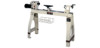
Read and understand the entire contents of this manual before attempting assembly or operation. Failure to comply may cause serious injury. 7.0 Setup and assembly 7.1 Shipping contents Carton contents (see Figure 2) 1 Lathe 2 Cast Legs 1 Tailstock 1 Headstock 1 Tool Rest Body 1 Tool Basket 1 Guard Assembly 1 Accessory Package 1 Owner's Manual 1 Warranty Card Accessory Package Box: 1 Live Center 1 Rod for Live Center 1 Spur Center 1 Index Pin 1 Face Plate 1 Rod for Face Plate 1 Knockout Rod 1 Tool Rest 4 Adjustable Feet Tool Basket Bracket Hardware 2 Hex Sckt Cp Screws 5/16"-18 x 1-1/2" 4 Flat Washers 5/16" 2 Set Screws 1/4"-20 x 1/4" 3 Hex Nuts 5/16" 1 Set Screw 5/16"-18 x 5/8" Contents of Accessory Package 7.2 Unpacking and cleanup 1. Remove the shipping container. Do not discard any shipping material until the lathe is set up and running properly. 2. Remove hex cap bolts from skid bottom and move the lathe off the skid and into position. 3. Clean all rust protected surfaces with a cleaner degreaser. Clean thoroughly under the headstock, tailstock and tool rest body. 7.3 Installing adjustable feet 1. Secure tool rest (A, Figure 1) to tool rest body (B, Figure 1) by tightening handle (C, Figure 1). Figure 1 2. Slide the tailstock and tool rest to the headstock end of the lathe bed. See "Controls and Features" section of this manual on how to move the tailstock and tool rest. 3. Lift the tailstock end of the lathe up far enough to slide a few pieces of scrap wood under the leg, see Figure 2. 4. Thread adjustable feet (A, Figure 2) into stand leg (B, Figure 2). There is a flat spot on the shaft near the foot that will accommodate a wrench. Thread a hex nut (C, Figure 2) onto shaft and leave loose for now. 5. Remove the scrap pieces of wood and slide the tailstock, tool rest and headstock down to the tailstock end of the lathe bed. 6. Mount the two adjustable feet in the same manner as above and return the headstock, tool rest and tailstock to their normal positions. 7. Adjust the feet so that the lathe rests evenly on the floor, and tighten the nuts. 9
-
 1
1 -
2
-
3
-
 4
4 -
 5
5 -
 6
6 -
 7
7 -
 8
8 -
 9
9 -
 10
10 -
 11
11 -
 12
12 -
 13
13 -
 14
14 -
15
-
16
-
17
-
18
-
19
-
20
-
21
-
22
-
23
-
24
-
25
-
26
-
27
-
28
 |
 |
