JVC GR-DVX507A Instruction Manual - Page 95

JVC GR-DVX507A - Camcorder - 800 KP Manual

Page 95 highlights

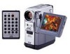
EN 95 Controls a •Power Zoom Ring [T/W]...੬ pg. 20 •Speaker Volume Control...੬ pg. 22 b Recording Start/Stop Button ...੬ pg. 19 c Power Switch [A, M, P, OFF]...੬ pg. 14 d Lock Button ...੬ pg. 14 e •Snapshot Button [SNAPSHOT] ...੬ pg. 27, 53 •Information Button [INFO] (GR-DVX707/507 only) ...੬ pg. 30 f •E-Mail Clip Recording Button [E-MAIL] (GR-DVX707 only)...੬ pg. 60, 61 •Index Button [INDEX] (GR-DVX707/507 only) ...੬ pg. 30, 59, 71 •Exposure Button [EXPOSURE] (GR-DVX407/400 only) ...੬ pg. 56 g •Menu Wheel [MENU pg. 38 •LCD Monitor Brightness Control [BRIGHT pg. 13 h Battery Release Tab [BATT.RELEASE]...੬ pg. 10 i Cassette Open/Eject Switch [OPEN/EJECT]...੬ pg. 16 j •Play/Pause Button [4/9] ...੬ pg. 22 •Backlight Compensation Button [BACKLIGHT] ...੬ pg. 57 k •Fast-Forward Button [5]...੬ pg. 22 •Night-Scope Button [NIGHT] ...੬ pg. 53 l VIDEO/MEMORY Switch [VIDEO/MEMORY] (GR-DVX707/507 only) ...੬ pg. 14 m •Rewind Button [3] ...੬ pg. 22 •Focus Adjustment Button [FOCUS] ...੬ pg. 55 n •Stop Button [8] ...੬ pg. 22 •Digital Sound Button [D.SOUND] (GR-DVX707 only)...੬ pg. 59 •D.S.C. Playback Select Button [SELECT] (GR-DVX707 only)...੬ pg. 28 - 34 o Dioptre Adjustment Control ...੬ pg. 12 U •USB (Universal Serial Bus) Connector (GR-DVX707/507 only) ...੬ pg. 78 •PC Connector (GR-DVX407/400 only) ...੬ pg. 78 V Digital Video Connector [DV IN/OUT (GR-DVX707/507/407) or DV OUT (GR-DVX400)] (i.link*) ...੬ pg. 63, 64, 78 * i.Link refers to the IEEE1394-1995 industry specification and extensions thereof. The logo is used for products compliant with the i.Link standard. Indicators A Power Lamp [POWER]...੬ pg. 14, 19 B Charge Lamp [CHARGE] ...੬ pg. 10 C Tally Lamp ...੬ pg. 19, 48 Other Parts a b c d e f g h i j k l m n o p LCD Monitor ...੬ pg. 13, 20 Viewfinder...੬ pg. 12 Viewfinder Cleaning Hatch ...੬ pg. 91 Speaker ...੬ pg. 22 Cassette Holder Cover...੬ pg. 16 Grip Belt Eyelet ...੬ pg. 6 Camera Sensor Be careful not to cover this area, a sensor necessary for shooting is built-in here. Stereo Microphone...੬ pg. 70 Lens Flash Sensor (GR-DVX707/507 only) Be careful not to cover this area, as it contains a sensor required by the flash. Flash (GR-DVX707/507 only) ...੬ pg. 54 Remote Sensor ...੬ pg. 66 Card Cover [MEMORY CARD] (GR-DVX707/507 only) ...੬ pg. 17 Battery Pack Mount ...੬ pg. 10 Stud Hole Tripod Mounting Socket ...੬ pg. 13 Connectors The connectors are located beneath the covers. P S-Video Output Connector [S-VIDEO]...੬ pg. 24, 62, 74 Q •Edit Connector [EDIT] (GR-DVX707/507 only) ...੬ pg. 74 •J Terminal [JLIP (Joint Level Interface Protocol)] (GR-DVX407/400 only)...੬ pg. 74 You can also connect to a JLIP-compatible camcorder or VCR to control it from the computer using the optional Software HSV16KITE. R Headphone Connector [ ] (GR-DVX707 only)...੬ pg. 70 No sound is output from the speaker when headphones are connected to this connector. S Audio/Video Output Connector [AV] ...੬ pg. 24, 62, 74 T DC Input Connector [DC] ...੬ pg. 10, 11

  • 1
  • 2
  • 3
  • 4
  • 5
  • 6
  • 7
  • 8
  • 9
  • 10
  • 11
  • 12
  • 13
  • 14
  • 15
  • 16
  • 17
  • 18
  • 19
  • 20
  • 21
  • 22
  • 23
  • 24
  • 25
  • 26
  • 27
  • 28
  • 29
  • 30
  • 31
  • 32
  • 33
  • 34
  • 35
  • 36
  • 37
  • 38
  • 39
  • 40
  • 41
  • 42
  • 43
  • 44
  • 45
  • 46
  • 47
  • 48
  • 49
  • 50
  • 51
  • 52
  • 53
  • 54
  • 55
  • 56
  • 57
  • 58
  • 59
  • 60
  • 61
  • 62
  • 63
  • 64
  • 65
  • 66
  • 67
  • 68
  • 69
  • 70
  • 71
  • 72
  • 73
  • 74
  • 75
  • 76
  • 77
  • 78
  • 79
  • 80
  • 81
  • 82
  • 83
  • 84
  • 85
  • 86
  • 87
  • 88
  • 89
  • 90
  • 91
  • 92
  • 93
  • 94
  • 95
  • 96
  • 97
  • 98
  • 99
  • 100
  • 101
  • 102
  • 103
  • 104

EN
95
Controls
a
•Power Zoom Ring [T/W]
....................
±
pg. 20
•Speaker Volume Control
....................
±
pg. 22
b
Recording Start/Stop Button
................
±
pg. 19
c
Power Switch [
A
,
M
,
P
, OFF]
..........
±
pg. 14
d
Lock Button
.........................................
±
pg. 14
e
•Snapshot Button [SNAPSHOT]
....
±
pg. 27, 53
•Information Button [INFO] (GR-DVX707/507
only)
..................................................
±
pg. 30
f
•E-Mail Clip Recording Button [E-MAIL]
(GR-DVX707 only)
.......................
±
pg. 60, 61
•Index Button [INDEX]
(GR-DVX707/507 only)
.........
±
pg. 30, 59, 71
•Exposure Button [EXPOSURE]
(GR-DVX407/400 only)
.....................
±
pg. 56
g
•Menu Wheel [MENU, +,–]
.................
±
pg. 38
•LCD Monitor Brightness Control
[BRIGHT, +,–]
....................................
±
pg. 13
h
Battery Release Tab [BATT.RELEASE]
....
±
pg. 10
i
Cassette Open/Eject Switch
[OPEN/EJECT]
......................................
±
pg. 16
j
•Play/Pause Button [
4
/
9
]
..................
±
pg. 22
•Backlight Compensation Button
[BACKLIGHT]
....................................
±
pg. 57
k
•Fast-Forward Button [
5
]
................
±
pg. 22
•Night-Scope Button [NIGHT]
............
±
pg. 53
l
VIDEO/MEMORY Switch [VIDEO/MEMORY]
(GR-DVX707/507 only)
.......................
±
pg. 14
m
•Rewind Button [
3
]
........................
±
pg. 22
•Focus Adjustment Button
[FOCUS]
............................................
±
pg. 55
n
•Stop Button [
8
]
.................................
±
pg. 22
•Digital Sound Button [D.SOUND]
(GR-DVX707 only)
.............................
±
pg. 59
•D.S.C. Playback Select Button [SELECT]
(GR-DVX707 only)
.....................
±
pg. 28 – 34
o
Dioptre Adjustment Control
................
±
pg. 12
Connectors
The connectors are located beneath the covers.
P
S-Video Output Connector
[S-VIDEO]
................................
±
pg. 24, 62, 74
Q
•Edit Connector [EDIT]
(GR-DVX707/507 only)
.....................
±
pg. 74
•J Terminal [JLIP (Joint Level Interface
Protocol)] (GR-DVX407/400 only)
.....
±
pg. 74
You can also connect to a JLIP-compatible
camcorder or VCR to control it from the
computer using the optional Software HS-
V16KITE.
R
Headphone Connector [
]
(GR-DVX707 only)
...............................
±
pg. 70
No sound is output from the speaker when
headphones are connected to this connector.
S
Audio/Video Output Connector
[AV]
.........................................
±
pg. 24, 62, 74
T
DC Input Connector [DC]
.............
±
pg. 10, 11
U
•USB (Universal Serial Bus) Connector
(GR-DVX707/507 only)
......................
±
pg. 78
•PC Connector
(GR-DVX407/400 only)
.....................
±
pg. 78
V
Digital Video Connector [DV IN/OUT
(GR-DVX707/507/407) or DV OUT
(GR-DVX400)] (i.link*)
.............
±
pg. 63, 64, 78
* i.Link refers to the IEEE1394-1995 industry
specification and extensions thereof. The logo
is used for products compliant with the i.Link
standard.
Indicators
A
Power Lamp [POWER]
....................
±
pg. 14, 19
B
Charge Lamp [CHARGE]
......................
±
pg. 10
C
Tally Lamp
......................................
±
pg. 19, 48
Other Parts
a
LCD Monitor
..................................
±
pg. 13, 20
b
Viewfinder
............................................
±
pg. 12
c
Viewfinder Cleaning Hatch
..................
±
pg. 91
d
Speaker
................................................
±
pg. 22
e
Cassette Holder Cover
..........................
±
pg. 16
f
Grip Belt Eyelet
......................................
±
pg. 6
g
Camera Sensor
Be careful not to cover this area, a sensor
necessary for shooting is built-in here.
h
Stereo Microphone
...............................
±
pg. 70
i
Lens
j
Flash Sensor (GR-DVX707/507 only)
Be careful not to cover this area, as it contains a
sensor required by the flash.
k
Flash (GR-DVX707/507 only)
...............
±
pg. 54
l
Remote Sensor
.....................................
±
pg. 66
m
Card Cover [MEMORY CARD]
(GR-DVX707/507 only)
........................
±
pg. 17
n
Battery Pack Mount
..............................
±
pg. 10
o
Stud Hole
p
Tripod Mounting Socket
.......................
±
pg. 13