JVC GY-X2BU Specifications - Page 8

q Powerswitch and Power indicator, QUICK REC] Quick-recording start/stop

Page 8 highlights

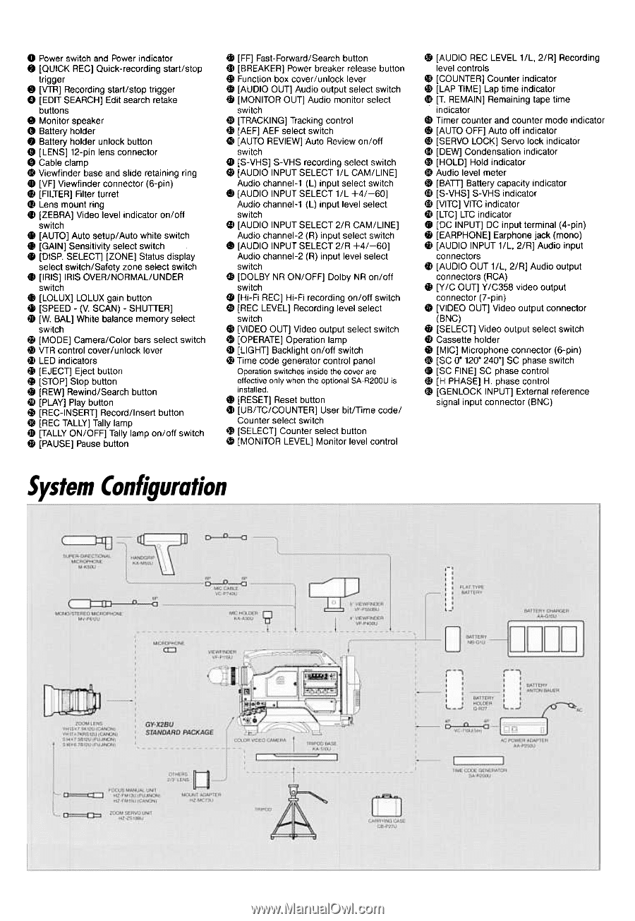
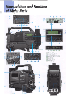
q Powerswitch and Powerindicator *, [QUICK REC] Quick-recording start/stop trigger [VTR] Recording start/stop trigger [EDIT SEARCH] Edit search retake buttons .Monitor speaker .Battery holder .Battery holder unlock button .[LENS] 12-pin lens connector .Cable clamp ~ Viewfinder base and slide retaining ring .[VF] Viewfinder connector (6-pin) .[FILTER] Filter turret .Lens mount ring 411[ZEBRA] Video level indicator on/off switch .[AUTO] Auto setup/ Auto white switch .[GAIN] Sensitivity select switch .[DISP. SELECT] [ZONE] Status display select switch/Safety zone select switch .[IRIS] IRIS OVER/NORMAL/UNDER switch .[LOLUX] LOLUX gain button .[SPEED -(V. SCAN) -SHUTTER] .[W. BAL] White balance memory select switch .[MODE] Camera/Color bars select switch 4! VTR control cover/unlock lever .LED indicators .[EJECT] Eject button ~ [STOP] Stop button .[REW] Rewind/Search button ~ [PLAY] Play button ~ [REC-INSERT] Record/Insert button 0> [REC TALLY] Tally lamp $ [TALLY ON/OFF] Tally lamp on/off switch ~ [PAUSE] Pause button @I [FF] Fast-Forward/Search button el [BREAKER] Power breaker release button .Function box cover/unlock lever $D [AUDIO OUT] Audio output select switch @D[MONITOR OUT] Audio monitor select switch e [TRACKING] Tracking control ~ [AEF] AEF select switch GDI[AUTO REVIEW] Auto Review on/off switch ED [S-VHS] S-VHS recording select switch fI [AUDIO INPUT SELECT 1/L CAM/LINE] Audio channel-1 (L) input select switch 8) [AUDIO INPUT SELECT 1/L +4/-60] Audio channel-1 (L) input level select switch 0} [AUDIO INPUT SELECT 2/R CAM/LINE] Audio channel-2 (R) input select switch Ell [AUDIO INPUT SELECT 2/R +4/-60] Audio channel-2 (R) input level select switch ~ [DOLBY NR ON/OFF] Dolby NR on/off switch ED [Hi-Fi REC] Hi-Fi recording on/off switch EB)[REC LEVEL] Recording level select switch Ei> [VIDEO OUT] Video output select switch «i> [OPERATE] Operation lamp ~ [LIGHT] Backlight on/off switch ~ Time code generator control panel Operation switches inside the cover are effective only when the optional SA-R200U is installed. II [RESET] Reset button .[UB/TC/COUNTER] User bit/Time code/ Counter select switch ~ [SELECT] Counter select button (p [MONITOR LEVEL] Monitor level control ~ [AUDIO REC LEVEL 1/L, 2/R] Recording level controls 4i) [COUNTER] Counter indicator t) [LAP TIME] Lap time indicator fm)[T. REMAIN] Remaining tape time indicator (I) Timer counter and counter mode indicator (f) [AUTO OFF] Auto off indicator @I [SERVO LOCK] Servo lock indicator ~ [DEW] Condensation indicator ~ [HOLD] Hold indicator ~ Audio level meter (j [BAn] Battery capacity indicator

  • 1
  • 2
  • 3
  • 4
  • 5
  • 6
  • 7
  • 8
  • 9
  • 10

~ [AUDIO REC LEVEL 1/L, 2/R] Recording
level controls
4i) [COUNTER] Counter indicator
t) [LAP TIME] Lap time indicator
fm)[T. REMAIN] Remaining tape time
indicator
(I) Timer counter and counter mode indicator
(f) [AUTO OFF] Auto off indicator
@I [SERVO LOCK] Servo lock indicator
~ [DEW] Condensation
indicator
~ [HOLD] Hold indicator
~ Audio level meter
(j [BAn]
Battery capacity indicator
<mI
[S-VHS] S-VHS indicator
(j) [VITC] VITC indicator
fj) [LTC] LTC indicator
.[DC
INPUT] DC input terminal (4-pin)
~ [EARPHONE] Earphone jack (mono)
fiI [AUDIO INPUT 1/L, 2/R] Audio input
connectors
tI [AUDIO OUT 1/L, 2/R] Audio output
connectors (RCA)
fj [y /C OUT] y /C358 video output
connector (7-pin)
~ [VIDEO OUT] Video output connector
(BNC)
"
[SELECT] Video output select switch
fi) Cassette holder
fiI [MIC] Microphone connector (6-pin)
tm>
[SC 0" 120" 240"] SC phase switch
ti [SC FINE] SC phase control
1$ [H PHASE] H. phase control
@) [GENLOCK INPUT] External reference
signal input connector (BNC)
q Powerswitch and Power indicator
,
[QUICK REC] Quick-recording start/stop
*
trigger
[VTR] Recording start/stop
trigger
[EDIT SEARCH] Edit search retake
buttons
.Monitor
speaker
.Battery
holder
.Battery
holder unlock button
.[LENS]
12-pin lens connector
.Cable
clamp
~ Viewfinder base and slide retaining ring
.[VF]
Viewfinder connector (6-pin)
.[FILTER]
Filter turret
.Lens
mount ring
411
[ZEBRA] Video level indicator on/off
switch
.[AUTO]
Auto setup/ Auto white switch
.[GAIN]
Sensitivity select switch
.[DISP.
SELECT] [ZONE] Status display
select switch/Safety
zone select switch
.[IRIS]
IRIS OVER/NORMAL/UNDER
switch
.[LOLUX]
LOLUX gain button
.[SPEED
-(V. SCAN) -SHUTTER]
.[W.
BAL] White balance memory select
switch
.[MODE]
Camera/Color
bars select switch
4! VTR control cover/unlock
lever
.LED
indicators
.[EJECT]
Eject button
~ [STOP] Stop button
.[REW]
Rewind/Search
button
~ [PLAY] Play button
~ [REC-INSERT] Record/Insert
button
0> [REC TALLY] Tally lamp
$ [TALLY ON/OFF] Tally lamp on/off switch
~ [PAUSE] Pause button
@I [FF] Fast-Forward/Search
button
el [BREAKER]
Power
breaker
release
button
.Function
box cover/unlock
lever
$D [AUDIO
OUT]
Audio
output
select
switch
@D
[MONITOR
OUT]
Audio
monitor
select
switch
e
[TRACKING]
Tracking
control
~
[AEF]
AEF select
switch
GDI
[AUTO
REVIEW]
Auto
Review
on/off
switch
ED [S-VHS]
S-VHS
recording
select
switch
fI
[AUDIO
INPUT
SELECT
1/L CAM/LINE]
Audio
channel-1
(L) input
select
switch
8) [AUDIO
INPUT
SELECT
1/L +4/-60]
Audio
channel-1
(L) input
level select
switch
0} [AUDIO
INPUT
SELECT
2/R CAM/LINE]
Audio
channel-2
(R) input
select
switch
Ell [AUDIO
INPUT
SELECT
2/R
+4/-60]
Audio
channel-2
(R) input
level select
switch
~
[DOLBY
NR ON/OFF]
Dolby
NR on/off
switch
ED [Hi-Fi
REC]
Hi-Fi recording
on/off
switch
EB)
[REC
LEVEL]
Recording
level select
switch
Ei> [VIDEO
OUT]
Video
output
select
switch
«i> [OPERATE]
Operation
lamp
~
[LIGHT]
Backlight
on/off
switch
~ Time
code
generator
control
panel
Operation switches inside the cover are
effective only when the optional SA-R200U is
installed.
II
[RESET]
Reset
button
.[UB/TC/COUNTER]
User
bit/Time
code/
Counter
select
switch
~
[SELECT]
Counter
select
button
(p [MONITOR
LEVEL]
Monitor
level control