JVC KD-R97MBS Instruction Manual - Page 38
Wiring connection, IMPORTANT
 |
View all JVC KD-R97MBS manuals
Add to My Manuals
Save this manual to your list of manuals |
Page 38 highlights
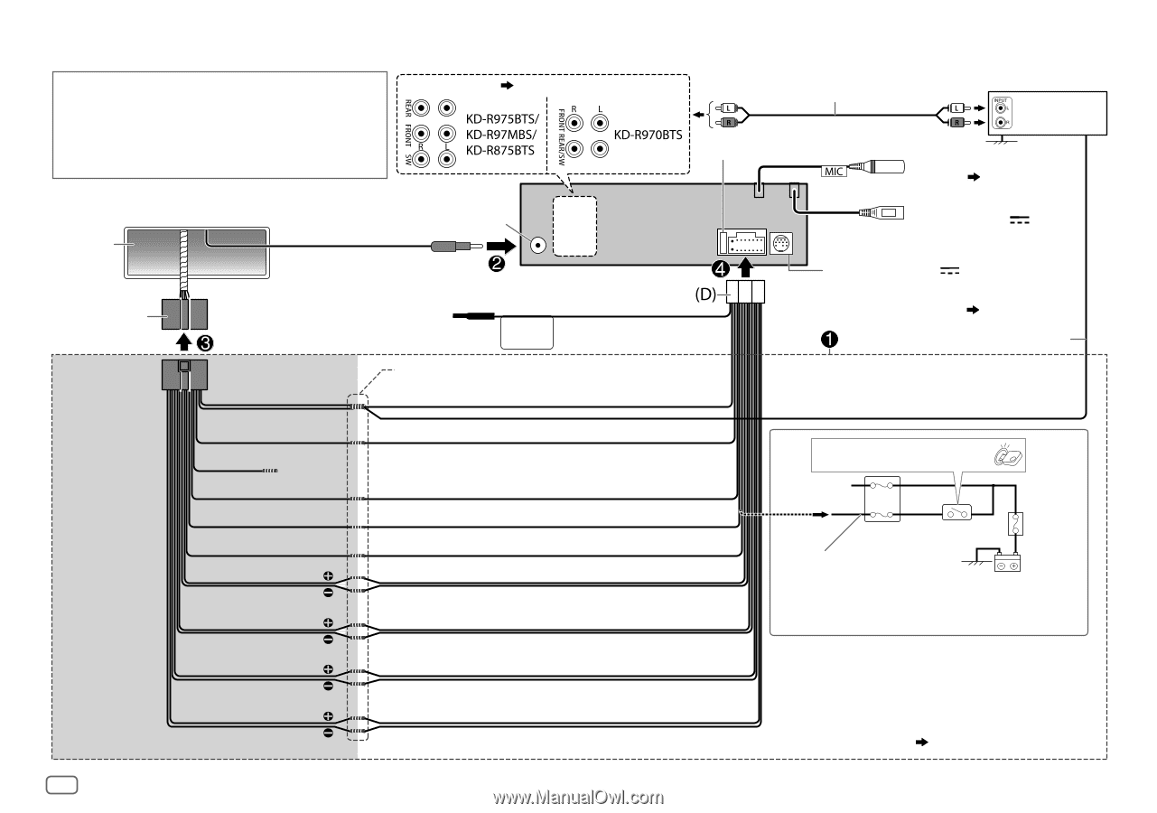
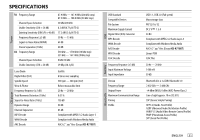
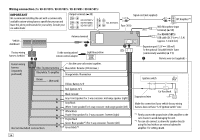
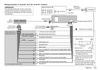
Wiring connection (for KD-R975BTS / KD-R970BTS / KD-R97MBS / KD-R875BTS) IMPORTANT We recommend installing the unit with a commercially available custom wiring harness specific for your car and leave this job to professionals for your safety. Consult your car audio dealer. Output terminals ( 33) Vehicle dashboard Antenna terminal Factory wiring harness (vehicle) To the steering wheel remote control adapter Light blue/yellow STEERING WHEEL REMOTE Signal cord (not supplied) JVC Amplifier*1 Fuse (10 A) MIC (Microphone input terminal) ( 14) (For KD-R975BTS) USB cable (DC 5 V 1.5 A) (approx. 1.2 m/4 feet) Expansion port (12 V 500 mA) To the optional SiriusXM Vehicle Tuner (commercially available) ( 11) Remote wire (not supplied) Custom wiring harness (separately purchased) Blue: To power antenna Blue/white: To amplifier Brown (Not used) Join the same color wires together. Blue/white: Remote (200 mA max.) Orange/white: Illumination Yellow: Battery 12 V Ignition switch Recommended connection Red: Ignition 12 V Black: Ground Gray: Front speaker/For 3-way crossover: mid range speaker (right) Gray/black White: Front speaker/For 3-way crossover: mid range speaker (left) White/black Purple: Rear speaker/For 3-way crossover: Tweeter (right) Purple/black Green: Rear speaker*2/For 3-way crossover: Tweeter (left) Green/black *2 Separate red wire Car fuse block Make this connection if your vehicle factory wiring harness does not have "12 V ignition switch" wire. *1 Firmly connect the ground wire of the amplifier to the car's chassis to avoid damaging the unit. *2 You can also connect a subwoofer speaker directly using this lead without an external subwoofer amplifier. For setting, 22. 34
-
 1
1 -
2
-
3
-
4
-
5
-
6
-
7
-
8
-
9
-
10
-
11
-
12
-
13
-
14
-
15
-
16
-
17
-
18
-
19
-
20
-
21
-
22
-
23
-
24
-
25
-
26
-
27
-
28
-
29
-
30
-
31
-
32
-
 33
33 -
 34
34 -
 35
35 -
 36
36 -
 37
37 -
 38
38 -
 39
39 -
 40
40 -
 41
41 -
 42
42 -
 43
43 -
44
-
45
-
46
-
47
-
48
-
49
-
50
-
51
-
52
-
53
-
54
-
55
-
56
-
57
-
58
-
59
-
60
-
61
-
62
-
63
-
64
-
65
-
66
-
67
-
68
-
69
-
70
-
71
-
72
-
73
-
74
-
75
-
76
-
77
-
78
-
79
-
80
-
81
-
82
-
83
-
84
-
85
-
86
-
87
-
88
-
89
-
90
-
91
-
92
-
93
-
94
-
95
-
96
-
97
-
98
-
99
-
100
-
101
-
102
-
103
-
104
-
105
-
106
-
107
-
108
 |
 |