JVC KS-AX3202 Instruction Manual - Page 2
Speaker Connections
 |
View all JVC KS-AX3202 manuals
Add to My Manuals
Save this manual to your list of manuals |
Page 2 highlights
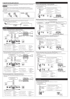
SPEAKER CONNECTIONS Connection varies depending on the number of the speakers used in your car. Select the appropriate connection referring to the following diagrams. Notes • Securely connect all the parts. If the connections are loose, due to contact resistance etc., heat will break out and may cause an accident. • Run the connection leads under the car mats to prevent accidental disconnections. Å When your receiver is equipped with line output. ı When your receiver is NOT equipped with line output. KS-AX3204 KS-AX3202 KS-AX3201D KS-AX3202 2-speaker system-Normal Mode • Use the speakers with an impedance of 2 Ω to 8 Ω. Å JVC car receiver, etc. ı Speaker input connector. Line out Connector lead a White "LEFT (+)" To Receiver = Left (+) lead b Black "RECEIVER GND" = Chassis*1 *2 c Gray "RIGHT (+)" = Right (+) lead FRONT REAR • Connect each lead of the speaker input connector to a speaker positive lead or chassis*1 of the receiver. • Cover the terminals of unused speaker negative leads of the receiver with insulating tape to prevent short circuits. *1 Example: connecting to the ground Black lead of the speaker input connector Rear ground terminal INPUT L /MONO R HIGH INPUT INPUT SENS. 1 2 0.5 3 4 5V 0.2V CROSSOVER CROSSOVER LPF HPF OFF LPF HPF OFF BRIDGE MODE R L SPEAKER OUTPUT 2-speaker system plus subwoofer • Use the speakers with an impedance of 2 Ω to 8 Ω. Line out (Rear) or Å JVC car receiver, etc. Subwoofer out *2 JVC amplifier, etc. (Purchased separately) *2 Not supplied RECEIVER GND KS-AX3204 4-speaker system-Normal Mode • Use the speakers with an impedance of 2 Ω to 8 Ω. Å JVC car receiver, etc. Front JVC car receiver, etc. BRIDGE MODE R FRONT L R REAR L Front CROSSOVER Line out (Front) *2 LPF HPF OFF Rear *2 Line out (Rear) SPEAKER OUTPUT Rear CROSSOVER LPF HPF OFF HIGH INPUT SENS. INPUT 2 1 0.5 3 4 5V 0.2V INPUT L /MONO L /MONO R R HIGH INPUT INPUT SENS. CROSSOVER 21 3 4 5V 0.5 LPF HPF 0.2V OFF CROSSOVER LPF HPF OFF FRONT REAR ı Speaker input connector. Connector lead To Receiver a White "FRONT LEFT (+)" = Front left (+) lead b Black "RECEIVER GND" = Chassis*1 c Gray "FRONT RIGHT (+)" = Front right (+) lead Connector lead To Receiver d Green "REAR LEFT (+)" = Rear left (+) lead e Black "RECEIVER GND" = Chassis*1 f Purple "REAR RIGHT (+)" = Rear right (+) lead 2-speaker system plus subwoofer-Bridge Mode • Use the speakers with an impedance of 2 Ω to 8 Ω. • Use the subwoofer with an impedance of 4 Ω to 8 Ω. Å JVC car receiver, etc. Front BRIDGE MODE R FRONT L R REAR L Front Line out (Front) SPEAKER OUTPUT CROSSOVER LPF HPF OFF CROSSOVER LPF HPF OFF Line out (Rear) or *2 *2 Subwoofer out HIGH INPUT SENS. INPUT 2 1 0.5 3 4 5V 0.2V INPUT L /MONO L /MONO R R HIGH INPUT INPUT SENS. CROSSOVER 21 3 4 5V 0.5 LPF HPF 0.2V OFF Subwoofer CROSSOVER LPF HPF OFF FRONT REAR ı Speaker input connector. Connector lead To Receiver a White "FRONT LEFT (+)" = Front left (+) lead b Black "RECEIVER GND" = Chassis*1 c Gray "FRONT RIGHT (+)" = Front right (+) lead Connector lead To Receiver d Green "REAR LEFT (+)" = Rear left (+) lead e Black "RECEIVER GND" = Chassis*1 f Purple "REAR RIGHT (+)" = Rear right (+) lead 2-speaker system-Bridge Mode • Use the speakers with an impedance of 4 Ω to 8 Ω. • Be sure to connect the line output from the receiver to the left (L) jack on this unit. Å JVC car receiver, etc. BRIDGE MODE R FRONT L R REAR L Front Front CROSSOVER LPF HPF OFF Line out *2 SPEAKER OUTPUT CROSSOVER LPF HPF OFF HIGH INPUT SENS. INPUT 2 1 0.5 3 4 5V 0.2V INPUT L /MONO L /MONO R R HIGH INPUT INPUT SENS. CROSSOVER 21 3 4 5V 0.5 LPF HPF 0.2V OFF CROSSOVER LPF HPF OFF FRONT ı Speaker input connector. Connector lead To Receiver a White "FRONT LEFT (+)" b Black "RECEIVER GND" c Gray "FRONT RIGHT (+)" = Front left (+) lead = Chassis*1 = Front left (+) lead REAR Connector lead To Receiver d Green "REAR LEFT (+)" = Front right (+) lead e Black "RECEIVER GND" = Chassis*1 f Purple "REAR RIGHT (+)" = Front right (+) lead Line out (Front) *2 ı Speaker input connector. Connector lead To Receiver a White "LEFT (+)" = Left (+) lead b Black "RECEIVER GND" = Chassis*1 c Gray "RIGHT (+)" = Right (+) lead Subwoofer INPUT L /MONO R HIGH INPUT INPUT SENS. 1 2 0.5 3 4 5V 0.2V CROSSOVER CROSSOVER LPF HPF OFF LPF HPF OFF BRIDGE MODE R L SPEAKER OUTPUT Subwoofer system-Bridge Mode • Use the speakers with an impedance of 4 Ω to 8 Ω. Å JVC car receiver, etc. ı Speaker input connector. Line out (Rear) or Subwoofer out *2 Connector lead a White "LEFT (+)" b Black "RECEIVER GND" c Gray "RIGHT (+)" To Receiver = Left (+) lead = Chassis*1 = Right (+) lead INPUT L /MONO R HIGH INPUT INPUT SENS. 1 2 0.5 3 4 5V 0.2V CROSSOVER CROSSOVER LPF HPF OFF LPF HPF OFF BRIDGE MODE R L SPEAKER OUTPUT Subwoofer 2-speaker system (2 amplifiers)-Bridge Mode • Use the speakers with an impedance of 4 Ω to 8 Ω. • Be sure to connect the line output from the receiver to the left (L) jack on this unit. Å JVC car receiver, etc. ı Speaker input connector. Line out *2 INPUT L /MONO R HIGH INPUT INPUT SENS. 1 2 0.5 3 4 5V 0.2V Connector lead a White "LEFT (+)" b Black "RECEIVER GND" c Gray "RIGHT (+)" CROSSOVER LPF HPF OFF CROSSOVER To Receiver = Front right (+) lead = Chassis*1 = Front right (+) lead BRIDGE MODE R L LPF HPF OFF SPEAKER OUTPUT INPUT L /MONO R HIGH INPUT INPUT SENS. 1 2 0.5 3 4 5V 0.2V CROSSOVER LPF HPF OFF ı Speaker input connector. Connector lead To Receiver a White "LEFT (+)" = Front left (+) lead b Black "RECEIVER GND" = Chassis*1 c Gray "RIGHT (+)" = Front left (+) lead BRIDGE MODE R L SPEAKER OUTPUT KS-AX3201D Subwoofer system • Use the speakers with an impedance of 2 Ω to 8 Ω. Å JVC car receiver, etc. Line out (Rear) or Subwoofer out *2 PRE OUT L INPUT L /MONO HIGH INPUT ı Speaker input connector. Connector lead To Receiver a White "LEFT (+)" = Left (+) lead b Black "RECEIVER GND" = Chassis*1 c Gray "RIGHT (+)" = Right (+) lead R R 2 SPEAKER OUTPUT Subwoofer
-
 1
1 -
 2
2 -
 3
3 -
 4
4 -
 5
5 -
 6
6
 |
 |