JVC PC-XC350 Service Manual
JVC PC-XC350 Manual
 |
View all JVC PC-XC350 manuals
Add to My Manuals
Save this manual to your list of manuals |
JVC PC-XC350 manual content summary:
- JVC PC-XC350 | Service Manual - Page 1
PC-XC350 SERVICE MANUAL CD PORTABLE COMPONEMT SYSTEM PC-XC350 Unit No. SP-PCXC350 contents Safety precaution 1-2 Disassembly method 1-4 Adjustment method 1-6 TOC read 1-11 Major IC Description 1-12 Unit No. SP-PCXC350 Unit No. SP- - JVC PC-XC350 | Service Manual - Page 2
PC-XC350 Safety Precautions 1. This design of this product contains special hardware and does not have the same safety characteristics as the recommended replacement parts shown in the Parts List of Service manual may create shock, fire, or other hazards. 4. The leads in the products are routed and - JVC PC-XC350 | Service Manual - Page 3
PC-XC350 Preventing static electricity Electrostatic discharge (ESD), which occurs when static electricity stored in the body, fabric, etc. is discharged, can destroy the laser diode in - JVC PC-XC350 | Service Manual - Page 4
PC-XC350 Disaeesmbly method Removing the rear panel 1. From behind the body, remove the eight screws A retaining the rear panel. 2. Then remove the two screws B retaining the - JVC PC-XC350 | Service Manual - Page 5
crew F retaing the control PCB left side. E 4. Remove the srews G retaing on the 3CD mechanism cover & the two screws H retaining on the control PCB F PC-XC350 G H Removing the Main PCB 1. Remove rear panel 2. Remove the 3CD mechanism 3. Remove the four screws attaching the main PCB. 1 - 5 - JVC PC-XC350 | Service Manual - Page 6
PC-XC350 Adjustment method Measurement instruments required for Tuner section adjustment Voltage applied to tuner ----- +B:DC 5.7V 1. Low frequency oscillator VT: FM 2~5v / am 1.5~7.5v This oscillator - JVC PC-XC350 | Service Manual - Page 7
of AM and FM to the frequency of cermic filter. Supply voltage: DC 12.0V Speaker impedance: 3 OHMS Function switch: RADIO PC-XC350 a. AM adjustment ste Adjusting Tuning circuit Frequency 1 IF 1000 KHz (450 KHz) BAND SELECT SWITCH : AM Input Connection Measurement input AM - JVC PC-XC350 | Service Manual - Page 8
PC-XC350 ARRANGEMENT OF ADJUSTMENTS POSITION 1 - 8 - JVC PC-XC350 | Service Manual - Page 9
PC-XC350 Tape recorder section Items Confirmation of head angle Confirmation of tape speed Measurement conditions Measurement method Test tape : TCC-182A(8KHz) Measurement output terminal : Speaker - JVC PC-XC350 | Service Manual - Page 10
PC-XC350 Electrical Performance Items Measurement conditions Adjustment of recording blas current (Reference Value) Mode: Playback mode Recording mode Test tape TDK-D60 Measurement output terminal : Both - JVC PC-XC350 | Service Manual - Page 11
PC-XC350 1-11 - JVC PC-XC350 | Service Manual - Page 12
PC-XC350 DESCRIPTION OF MAJOR IC TA2104BN (IC101) AM/FM 1 CHIP TUNER Block Diagram 1-12 - JVC PC-XC350 | Service Manual - Page 13
AN7345K (IC201) DUAL RECORD/PLAYBACK PRE-AMPLIFIER Block Diagram PC-XC350 1-13 - JVC PC-XC350 | Service Manual - Page 14
PC-XC350 1 - 14 - JVC PC-XC350 | Service Manual - Page 15
PC-XC350 1 - 15 - JVC PC-XC350 | Service Manual - Page 16
PC-XC350 BLOCK DIAGRAM 1 - 16
-
 1
1 -
 2
2 -
 3
3 -
 4
4 -
 5
5 -
 6
6 -
 7
7 -
8
-
9
-
10
-
11
-
12
-
13
-
14
-
15
-
16
 |
 |

PC-XC350
SERVICE MANUAL
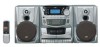
CD PORTABLE COMPONEMT SYSTEM
PC-XC350
contents
Safety precaution ------------------ 1-2
Block/Wiring Diagram ----------------- 1-16
Disassembly method -------------- 1-4
Circuit Diagram ------------------------- 1-18
Adjustment method ---------------- 1-6
PCB drawing ---------------------------- 1-20
TOC read ---------------------------- 1-11
Assembly -------------------------------- 1-22
Major IC Description ---------------1-12
Packing ----------------------------------- 1-32
No. xxxxx
COPYRIGHT © 2001 VICTOR COMPANY OF JAPAN,LTD (By JCA)
OCT 2001
Area Suffix
J-----USA
C-----CANADA
Unit No.
SP-PCXC350
Unit No.
SP-PCXC350
Unit No.
SP-PCXC350