JVC PC-XC350 Service Manual - Page 6
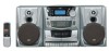
PC-XC350
 |
View all JVC PC-XC350 manuals
Add to My Manuals
Save this manual to your list of manuals |
Page 6 highlights
PC-XC350 Adjustment method Measurement instruments required for Tuner section adjustment Voltage applied to tuner ----- +B:DC 5.7V 1. Low frequency oscillator VT: FM 2~5v / am 1.5~7.5v This oscillator should have a capacity to output Reference measurement ----- 26.1mV(0.866/3 0dB to 600 at an oscillation frequency of output 50Hz-20KHz Input positions ----- AM : Standard loop antenna FM : TP1 (hot) and TP2 (GND) 2. Electronic voltmeter 3. Distorion meter 4. Frequency counter Standard measurement position of volumett 5. Wow & flutter meter 6. Test tape Bass Off TCC-112: tape speed and running unevenness (3KHz) EQ Flat TCC-140: Reference level (1KHz) UP and down adjustment of volume ----- Vol : 16 TCC-182A: Head angle (8KHz), playback frequency characteristics (1KHz) and dubbing frequency Precautions for measurement charateristics (125Hz and 8KHz) 1. Direct connect to the IF sweeper output side and 1 UF and 22 Kohm connect to the 7. Black tape sweeper input side. Same as FIG. 1. TYPE I : TDK-D60 8. Torque gauge : For play and tension FWD(CT-120m), and FF/REW(CT-F) Measurement conditions Power supply voltage----------AC 120V (60Hz) Reference output----------Speaker : 0.866V/3 Headphone : 0.245V/32 Reference frequency and -----1KHz, AUX : 450mV input level Input for confirming recording and-----CD : -10dB playback characteristics Measurement output terminal-----Speaker CN301 *Load resistance 3 Radio Input signal AM frequency 400Hz AM modulation 30% FM frequency 1 KHz FM frequency deviation --------22.5KHz 2. The IF sweeper output level should be made as low as possible within the adjusttable range. 3. Since the IF sweeper is a fixed device, there is no need to adjust this sweeper. 4. Since a ceramic oscillator is used, there is no need to perform and MIX adjustment. 5. Since a fixed coil is used, there is no need to adjust the FM tracking. 6. The input and output earth systems are separated. In case of simuitaneously measuring the voltage in both of the input and output systems with an electronic voltmeter for two channels, therefore, the earth should be connected particularly carefully. 7. In the case of BTLconnection amp., the minus terminal of speaker is not for earthing. Therefore, be sure not to connect any other earth terminal to this terminal. This system is of an BTL system. 8. For connecting a dummy resistor when measuring the output, use the wire with a greater code sze. 9. Whenever any mixed tape is used, use the band pass filter (DV-12V) 1 - 6
-
 1
1 -
 2
2 -
 3
3 -
 4
4 -
 5
5 -
 6
6 -
 7
7 -
 8
8 -
 9
9 -
 10
10 -
 11
11 -
 12
12 -
13
-
14
-
15
-
16
 |
 |
