JVC RX5032VSL Instruction Manual - Page 32
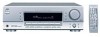
AV COMPU LINK Remote Control System - rx 5032vsl - av receiver
 |
UPC - 046838259463
View all JVC RX5032VSL manuals
Add to My Manuals
Save this manual to your list of manuals |
Page 32 highlights
AV COMPU LINK Remote Control System The AV COMPU LINK remote control system allows you to operate JVC's video components (TV, VCR, and DVD player) through the receiver. To use this remote control system, you need to connect the video components you want to operate following the diagrams below and the procedure on the next page. RX-6030VBK/RX-6032VSL This receiver is equipped with the AV COMPU LINK-III, which added a function to operate JVC's video components through the component video terminals. 7 AV COMPU LINK Connection Rear panel VCR VHS AV COMPU LINK DVD player DVD AV COMPU LINK AV COMPU LINK - III AV COMPU LINK III AV COMPU LINK EX TV Notes: • You can connect to the TV with the AV COMPU LINK III or AV COMPU LINK EX terminal. A TV with AV COMPU LINK RECEIVER/AMP terminal can not be used. • When connecting the receiver and a TV with the AV COMPU LINK EX terminal by using a component video cable, you cannot use the Automatic Selection of TV's Input Mode (see page 31). 7 Video cable connection • When connecting the DVD player and/or the VCR to the receiver using the composite video terminals, also connect this receiver to the TV's Video Input 2 terminals (composite video input) using composite video cables. • When connecting the DVD player and/or the VCR to the receiver using the S-video terminals, also connect this receiver to the TV's Video Input 1 terminals (S-video input) using S-video cables. • When connecting the DVD player and/or the VCR to the receiver using the component video terminals, also connect this receiver to the TV's Video Input 2 terminals (component video input) using component video cables. To use the AV COMPU LINK remote control system, set the video input terminal type for the DVD player and the VCR correctly (see "Selecting the Video Input Terminal-VIDEO IN DVD, VIDEO IN VCR" on page 16). RX-5030VBK/RX-5032VSL 7 AV COMPU LINK connection Rear panel VCR VHS AV COMPU LINK DVD player DVD AV COMPU LINK RIGHT AV COMPU LINK AV COMPU LINK EX AV COMPU LINK III TV Note: You can connect to the TV with the AV COMPU LINK EX or AV COMPU LINK III terminal. A TV with AV COMPU LINK RECEIVER/AMP terminal can not be used. 7 Video cable connection Connect the DVD player and/or the VCR to this receiver using the VIDEO (composite video) terminals, and connect this receiver to the TV's Video Input 2 terminals (composite video input) using composite video cables 30
-
 1
1 -
2
-
3
-
4
-
5
-
6
-
7
-
8
-
9
-
10
-
11
-
12
-
13
-
14
-
15
-
16
-
17
-
18
-
19
-
20
-
21
-
22
-
23
-
24
-
25
-
26
-
 27
27 -
 28
28 -
 29
29 -
 30
30 -
 31
31 -
 32
32 -
 33
33 -
 34
34 -
 35
35 -
 36
36 -
 37
37 -
38
-
39
-
40
-
41
-
42
-
43
-
44
-
45
-
46
-
47
-
48
-
49
-
50
-
51
-
52
-
53
-
54
-
55
-
56
-
57
-
58
-
59
-
60
-
61
-
62
-
63
-
64
-
65
-
66
-
67
-
68
-
69
-
70
-
71
-
72
-
73
-
74
-
75
-
76
-
77
-
78
-
79
-
80
-
81
-
82
-
83
-
84
-
85
-
86
-
87
 |
 |
