JVC TK-C920UA Instruction Manual - Page 7
Connection, Connecting the Power Supply Cable
 |
View all JVC TK-C920UA manuals
Add to My Manuals
Save this manual to your list of manuals |
Page 7 highlights
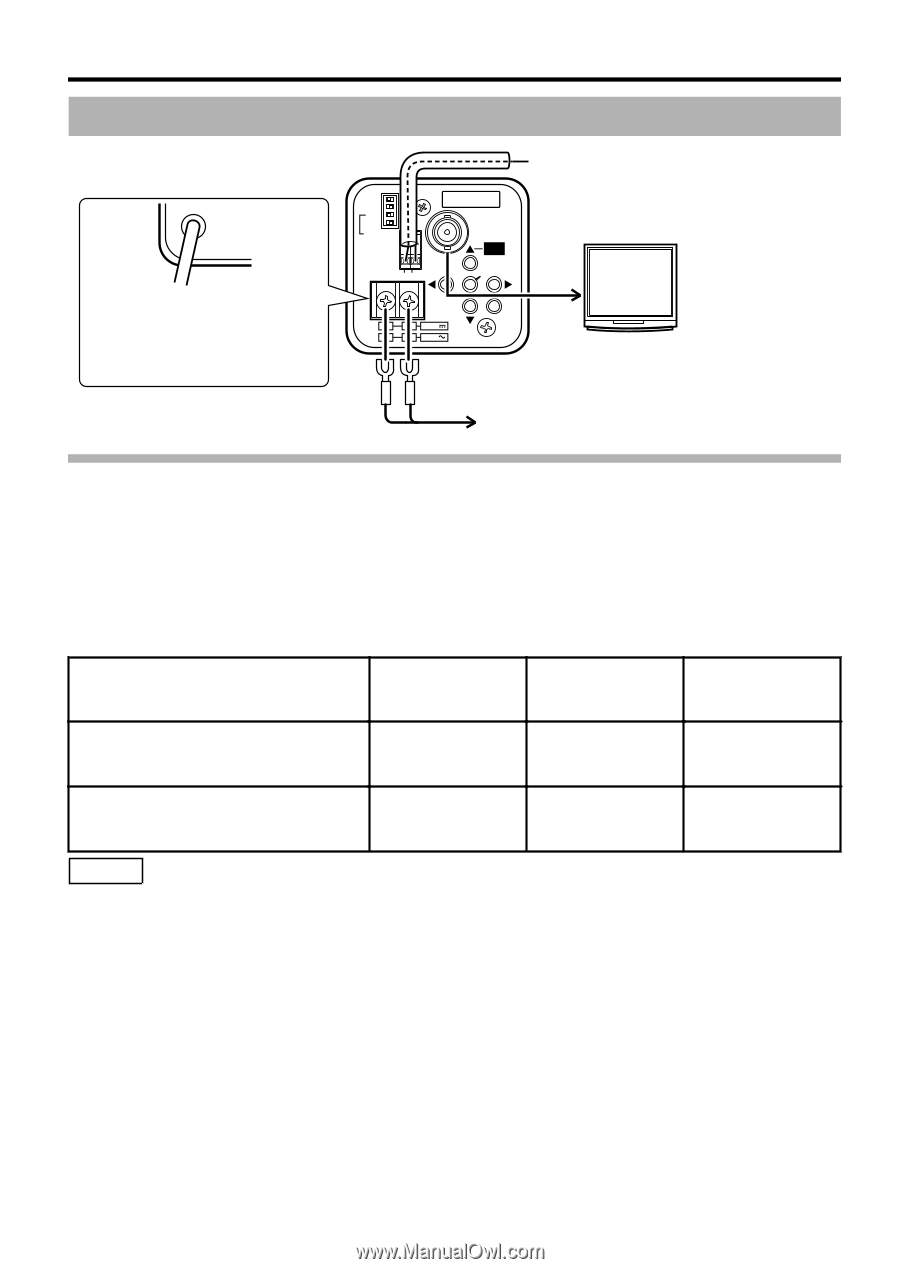
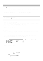
Connection/Installation . Connection Connect to AC 220 VAC 240 V power supply (TK-C9201EG/ TK-C9301EG) (A page 8) D/N AUTO ON BLC OFF ON LCD CRT AES OFF ON MONITOR TYPE CLASS 2 ONLY (U TYPE) ISOLATED POWER ONLY (E TYPE) AUX GND SEE INSTRUCTION MANUAL VIDEO OUT FOCUS ADJUST SET DC12V 1 2 AC24V MENU To the terminal of infrared illumination device etc. (TK-C9300U/TK-C9300E/ TK-C9301EG) (A page 8) Monitor (A page 8) Connect to AC 24V or DC 12V power supply (TK-C9200U/ TK-C9200E/TK-C9300U/TK-C9300E) (A page 7) Connecting the Power Supply Cable When power is supplied to the camera, the [POWER] lamp on the side panel lights up. m AC24 V or DC12 V (TK-C9200U/TK-C9200E/TK-C9300U/TK-C9300E) To prevent connection errors or a cable disconnection, use a lug plate to connect to the terminal. The following table shows the connection distances when 2-core VVF (vinyl-insulated vinyl sheath cables) are used. (Reference value) Conductor diameter (mm) Φ 1.0 and more Φ 1.6 and more Φ 2.0 and more Maximum connection distance: DC 12 V 50 m 140 m 220 m Maximum connection distance: AC 24 V 130 m 350 m 550 m Memo v If thin cables are used, the resistance of the cables will be high and a significant voltage drop will occur when the camera is at its maximum power consumption. Either use a thick cable with low resistance or place the power supply near to the camera and shorten the length of the cable to restrict the voltage drop at the rated current of camera to below 10 %. If voltage drop occurs during operation, the performance will be unstable. v Do not connect an AC 24 V cable to a commercial power supply. If it is connected by mistake, the internal circuit may be damaged. Sent the camera to the nearest JVC service center for inspection as the internal circuit may be damaged. 7
-
 1
1 -
 2
2 -
 3
3 -
 4
4 -
 5
5 -
 6
6 -
 7
7 -
 8
8 -
 9
9 -
 10
10 -
 11
11 -
 12
12 -
13
-
14
-
15
-
16
 |
 |