JVC VN-X35U other - Page 1
JVC VN-X35U - Network Camera Manual
 |
View all JVC VN-X35U manuals
Add to My Manuals
Save this manual to your list of manuals |
Page 1 highlights
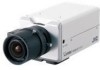
READ ME FIRST IP CAMERA VN-V25U/VN-V26U MEGAPIXEL IP CAMERA VN-X35U LST0744-001B Thank you for purchasing this JVC product. Before operating this unit, please read the instructions carefully to ensure the best possible performance. Ⅵ This manual contains the basic instructions for using this unit. Please refer to [INSTRUCTIONS](pdf) and [INSTRUCTIONS (Setting)](pdf) in the CD-ROM supplied with this product for description on the detailed usage of this unit. For the latest information, please refer to the AREADMEB file in the CD-ROM supplied with this product. ● The supplied CD-ROM includes [INSTRUCTIONS](pdf), [INSTRUCTIONS (Setting)](pdf), [API Guide](pdf), [VSIP Guide](pdf), [Search tool] and [White Spot Correction Tool]. Ⅵ How to read this READ ME FIRST. ● All rights reserved by JVC. Unauthorized duplication or reprinting of this manual, in whole or in part, is strictly prohibited. ● Windows is a registered trademark of Microsoft Corporation in the U.S ● All other product names used in this manual are trademarks or registered trademarks of their respective companies. Marks such as ீ, ா and have been omitted in this manual. ● Illustrated designs, specifications and other contents of this manual are subject to changes for improvement without prior notice. Check the Accessories/Attachments. ● Read Me First ● CD-ROM ● Warranty Card (For USA) ● Service Information Card(For USA) IMPORTANT SAFEGUARDS 1. Read all of these instructions. 2. Save these instructions for later use. 3. All warnings on the product and in the operating instructions should be adhered to. 4. Unplug this appliance system from the wall outlet before cleaning. Do not use liquid cleaners or aerosol cleaners. Use a damp cloth for cleaning. 5. Do not use attachments not recommended by the appliance manufacturer as they may cause hazards. 6. Do not use this appliance near water - for example, near a bathtub, washbowl, kitchen sink, or laundry tub, in a wet basement, or near a swimming pool, etc. 7. Do not place this appliance on an unstable cart, stand, or table. The appliance may fall, causing serious injury to a child or adult, and serious damage to the appliance. PORTABLE CART WARNING (symbol provided by RETAC) Use only with a cart or stand recommended by the manufacturer, or sold with the appliance. Wall or shelf mounting should follow the manufacturer's instructions, and should use a mounting kit approved by the manufacturer. An appliance and cart combination should be moved with care. Quick stops, excessive force, and uneven surfaces may cause the appliance and cart combination to overturn. 8. Slots and openings in the cabinet and the back or bottom are provided for ventilation, and to insure reliable operation of the appliance and to protect it from S3125A overheating, these openings must not be blocked or covered. The openings should never be blocked by placing the appliance on a bed, sofa, rug, or other similar surface. This appliance should never be placed near or over a radiator or heat register. This appliance should not be placed in a built-in installation such as a bookcase unless proper ventilation is provided. 9. This appliance should be operated only from the type of power source indicated on the marking label. If you are not sure of the type of power supplied to your home, consult your dealer or local power company. For appliance designed to operate from battery power, refer to the operating instructions. 10.For added protection for this product during a lightning storm, or when it is left unattended and unused for long periods of time, unplug it from the wall outlet and disconnect the antenna or cable system. This will prevent damage to the product due to lightning and power-line surges. 11.Do not allow anything to rest on the power cord. Do not locate this appliance where the cord will be abused by persons walking on it. 12.Follow all warnings and instructions marked on the appliance. 13.Do not overload wall outlets and extension cords as this can result in fire or electric shock. 14.Never push objects of any kind into this appliance through cabinet slots as they may touch dangerous voltage points or short out parts that could result in a fire or electric shock. Never spill liquid of any kind on the appliance. 15.Do not attempt to service this appliance yourself as opening or removing covers may expose you to dangerous voltage or other hazards. Refer all servicing to qualified service personnel. 16.Unplug this appliance from the wall outlet and refer servicing to qualified service personnel under the following conditions: a. When the power cord or plug is damaged or frayed. b. If liquid has been spilled into the appliance. c. If the appliance has been exposed to rain or water. d. If the appliance does not operate normally by following the operating instructions. Adjust only those controls that are covered by the operating instructions as improper adjustment of other controls may result in damage and will often require extensive work by a qualified technician to restore the appliance to normal operation. e. If the appliance has been dropped or the cabinet has been damaged. f. When the appliance exhibits a distinct change in performance - this indicates a need for service. 17.When replacement parts are required, be sure the service technician has used replacement parts specified by the manufacturer that have the same characteristics as the original part. Unauthorized substitutions may result in fire, electric shock, or other hazards. 18.Upon completion of any service or repairs to this appliance, ask the service technician to perform routine safety checks to determine that the appliance is in safe operating condition. Attention: This symbol is only valid in the European Union. Information for Users on Disposal of Old Equipment [European Union] This symbol indicates that the electrical and electronic equipment should not be disposed as general household waste at its end-of-life. Instead, the product should be handed over to the applicable collection point for the recycling of electrical and electronic equipment for proper treatment, recovery and recycling in accordance with your national legislation. By disposing of this product correctly, you will help to conserve natural resources and will help prevent potential negative effects on the environment and human health which could otherwise be caused by inappropriate waste handling of this product. For more information about collection point and recycling of this product, please contact your local municipal office, your household waste disposal service or the shop where you purchased the product. Penalties may be applicable for incorrect disposal of this waste, in accordance with national legislation. (Business users) If you wish to dispose of this product, please visit our web page www.jvc-europe.com to obtain information about the take-back of the product. [Other Countries outside the European Union] If you wish to dispose of this product, please do so in accordance with applicable national legislation or other rules in your country for the treatment of old electrical and electronic equipment. FOR USA AND CANADA CAUTION RISK OF ELECTRIC SHOCK DO NOT OPEN CAUTION:TO REDUCE THE RISK OF ELECTRIC SHOCK. DO NOT REMOVE COVER (OR BACK). NO USER-SERVICEABLE PARTS INSIDE.REFER SERVICING TO QUALIFIED SERVICE PERSONNEL. The lightning flash wish arrowhead symbol, within an equilateral triangle is intended to alert the user to the presence of uninsulated "dangerous voltage" within the product's enclosure that age" within the product's enclosure that may be of sufficient magnitude to constitute a risk of electric shock to persons. The exclamation point within an equilateral triangle is intended to alert the user to the presence of important operating and maintenance (servicing) instructions in the literature accompanying the appliance. Information for USA This device complies with part 15 of the FCC Rules. Changes or modifications not approved by JVC could void the user's authority to operate the equipment. This equipment has been tested and found to comply with the limits for a Class A digital device, pursuant to Part 15 of the FCC Rules. These limits are designed to provide reasonable protection against harmful interference when the equipment is operated in a commercial environment. This equipment generates, uses, and can radiate radio frequency energy and, if not installed and used in accordance with the instruction manual, may cause harmful interference to radio communications. Operation of this equipment in a residential area is likely to cause harmful interference in which case the user will be required to correct the interference at his own expense. This device complies with Part 15 of the FCC Rules. Operation is subject to the following two conditions: (1)This device may not cause harmful interference, and (2) this device must accept any interference received, including interference that may cause undesired operation. Due to design modifications, data given in this instruction book are subject to possible change without prior notice. WARNING: TO REDUCE THE RISK OF FIRE OR ELECTRIC SHOCK, DO NOT EXPOSE THIS APPLIANCE TO RAIN OR MOISTURE. AVERITISSEMENT: POUR EVITERLES RISQUES D'INCENDIE OU D'ELECTROCUTION, NE PAS EXPOSER L'APPAREILA L'HUMIDITE OU A LA PLUIE. INFORMATION (FOR CANADA) RENSEIGNEMENT (POUR CANADA) This Class A digital apparatus complies with Canadian ICES-003. Cet appareil num rique de la Class A est WARNING (FOR EUROPE): This is a Class A product. In a domestic environment this product may cause radio interference in which case the user may be required to take adequate measures. FOR USA-California Only This product contains a CR Coin Cell Lithium Battery which contains Perchlorate Material - special handling may apply. See www.dtsc.ca.gov/hazardouswaste/perchlorate ● This installation should be made by a qualified service person and should conform to all local codes. ● This installation shall be in accordance with the National Electrical Code, ANSI/NFPA 70. The unit is to be powered by an AC 24 V power supply or using the PoE. The AC 24 V power supply should conform to the following: Class 2 only (For USA), Isolated power supply only (For Europe and other). ● Any Mention in this manual of Alarm inputs/outputs have not been evaluated by UL to be used for Burglar Alarm Functionality. Ⅵ The latest version Please visit V.NETWORKS web site to check the latest firmware at http://www.jvc-victor.co.jp/english/products-e.html (The latest firmware can be found on V.NETWORKS B download page) Operating Environment Recommended Computer Specifications OS CPU VN-V25U/VN-V26U VN-X35U Memory capacity Free hard disk space Display and video card VN-V25U/VN-V26U VN-X35U Web browser : Windows XP (Professional or Home Edition)(SP2) : Windows Vista Business (SP1) Pentium4 1.5 GHz or higher : Pentium4 2 GHz or higher : 1 GB or more : 512 MB or more : 1024x768 pixels or larger, True Color (24 or 32 bits) VRAM 8 MB or more (256 MB and above recommended) : 1600 x 1200 pixels or larger, True Color (24 bits or 32 bits) VRAM 8 MB or more (256 MB and above recommended) : Internet Explorer XP : Version 6.0 Vista : Version 7.0 LAN Environment ● 10BASE-T/100BASE-TX network interconnected using devices such as an IEEE802.3-compliant switching hub. ● IEEE802.3af-compliant switching hub when PoE is in use. ● IGMPv2-compliant network when multicast is in use. Memoɿ ● To use MPEG4 images on the built-in viewer, install the open source codec AffdshowB. You can download AffdshowB from the Internet. JVC is not responsible for any damages resulting from your use of open source software. *The model illustrated in the diagram is VN-X35U. [MONITOR OUT] Selection Switch [RESET] Button [STATUS] Indicator MONITOR OUT PAL OFF NTSC RESET STATUS IRIS To AC 24 V Power Supply B E Push G Video Cable A 13 24 C LAN Cable 5 mm and above 7 mm and below D Mini jack Cable (VN-X35U/VN-V26U only) 1/4-20UNC F Fall Prevention Wire 6 mm Camera Mounting Bracket Anti-rotation Hole Camera Mounting Bracket 2 mm and below Camera Mounting Bracket Fastening Screw (2 pcs: M2.6 x 6 mm) Connection of Camera A Mounting the Lens Memoɿ ● Make use of a megapixel lens. (VN-X35U only) 1 Turn the lens in the clockwise direction to mount it to the camera firmly 2 When using a DC iris lens, pay attention to the pin position before connecting the lens cable Pin No. DC Iris Lens (Without Built-in EE Amplifier) 1 Damping (-) 2 Damping (+) 3 Driving (+) 4 Driving (-) B Power Connection Electricity can be supplied to this product either by connecting to the AC 24 V power supply or using the PoE. ● When power is supplied to this product, the [STATUS] indicator at the side lights up. The indicator lights up in orange color during startup, and switches to green color after startup is complete. Ⅵ POWER Cable : Connection distance when using 2-core VVF cable (reference values) Conductor Diameter (AWG No.) Maximum Extension VN-V25U VN-V26U VN-X35U R1.0 mm(18) and above 150 m 90 m 140 m R1.6 mm(14) and above 400 m 240 m 360 m R2.0 mm(12) and above 630 m 370 m 570 m Noteɿ ● Make sure to select only one mode of electrical supply. Connecting the power cord and the LAN cable for the PoE at the same time may result in failure or malfunction of the camera. ● By default the IP addresses of all the cameras are set to 192.168.0.2. If the power of multiple cameras within the same LAN environment are turned on at the same time, the IP addresses of the cameras overlap, thus preventing proper access. As such, make sure to turn on the power of the cameras one by one and set the IP addresses such that there is no overlapping. Warning The rated power of this product is AC 24 V, 50 Hz/60 Hz. Make sure to use it with the correct voltage. Use an AC 24 V supply that is isolated from the primary power supply. Supplying a power beyond the rated value may result in failures, smoke or fire. When the camera breaks down, turn off the power and contact our service center immediately. When a power beyond the rated value is supplied, the internal components may be damaged even if no abnormality is found on the appearance and operation of the camera. Please contact our service center immediately for servicing (charged separately). C LAN Cable Connection Connect the camera to a hub or computer using a LAN cable. ● When connecting to a hub : Make use of a straight cable. ● When connecting to a computer : Make use of a cross cable. Cable to use ● STP (Recommended shield cable) ● Length of 100 m or shorter ● Category 5 and above Memoɿ ● To distribute images and audio to the network, set the [MONITOR OUT] selection switch at the side of this product to AOFFB, then reboot the camera by turning off and on the power or pressing the [RESET] button for less than 2 seconds. ● PoE : class2 (VN-V25U) class0 (VN-V26U/VN-X35U) D Audio Signal Input/Output Terminal Connection (VN-V26U/VN-X35U only) Connect the mini jack R3.5 stereo cable. L ch : Connect to speakers with built-in amplifier, etc. R ch : Connect to plug-in power type capacitor microphone (VN-X35U*) (Supply voltage : DC 2.7 V(typ.), Input impedance : 2.2 kK(typ.)) * For VN-V26U, audio signals are input from the built-in microphone on the side of its body. Noteɿ ● Make sure that the external microphone is connected to the R ch and not other channels. When the microphone jack is plugged directly into the unit's [AUDIO IN/ OUT] terminal, loud noises can be distributed to the network. ( A [INSTRUCTIONS] )(VN-X35U only) E Alarm Input/Output Terminal Connection Connect the alarm input/output terminals with external devices, such as a sensor or buzzer. Plug/Unplug the cable while pressing the button as shown in the diagram. Cable to use ● Shielded cable (Recommended) ● Length of 50 m or shorter Installation of Camera F Mounting the Camera Use the screw hole on the camera mounting bracket to mount this camera to a fixer or rotating platform. ● The camera mounting bracket is mounted on the bottom surface of the camera by default. To mount it to the top surface, do so by removing the two fastening screws from the camera mounting bracket. Make sure to fasten the screws firmly. Warning ● To prevent the camera from falling off, ensure that it is connected to a firm place (ceiling slab or channel) using a fall prevention wire. ● Pay also careful attention to the length, strength, wiring, and material (insulating properties) of the fall prevention wire to be used. The length used should be as short as possible within the permissible range of the mounting length. The wire should be strong enough to withstand the total weight of this product and the fixer. (Pay also attention to the finishing at the end of the wire.) ● Mount the fall prevention wire using the black screw at the rear of the camera unit. ● Designated screw for fastening of fall prevention wire (M3 x 6 mm): Screws beyond the specified length must not be used as doing so may damage the interior. G Monitor Signal Output Terminal Connection Make use of this terminal for camera angle adjustment during installation or focus adjustment in the Focus Assist mode. Connect it to devices such as a video monitor using a video cable (RCA). Memoɿ ● Select the signal system for the monitor output using the [MONITOR OUT] selection switch at the side of this product. ( ANTSCB or APALB) After adjusting the camera angle, set the switch to AOFFB. After changing the switch settings, press the Reset button for less than 2 seconds to reboot the camera. H Focus Adjustment If focus assist mode is used, lens iris will be opened to enable high precision focus adjustment. 1 Set the [MONITOR OUT] selection switch to NTSC or PAL 2 Reboot the camera by turning off and on the power or pressing the [RESET] button for less than 2 seconds 3 Press the [RESET] button for 2 seconds or longer, and release within 5 seconds ● Doing so switches to the Focus Assist mode. The [STATUS] indicator alternates lighting up in green color and orange color alternately. ● Iris is opened and edge is enhanced. In case of VN-X35U, central portion of the image is enlarged. 4 Shoot the object 5 Adjust the lens focus 6 Set the [MONITOR OUT] selection switch to OFF 7 Press the [RESET] button for less than 2 seconds to restart ● Focus assist mode is disabled. ● It takes about one minute for the camera to reboot. ● While rebooting, the [STATUS] indicator lights up in orange. Memoɿ ● To disable focus assist mode, press [RESET] button between 2 to 5 seconds. ● You can also enable the Focus Assist mode on the viewer. ( A [INSTRUCTIONS (Setting)] ) KContinued
-
 1
1 -
 2
2
 |
 |
