Jenn-Air JMW2430WS Dimension Guide - Page 1
Jenn-Air JMW2430WS Manual
 |
View all Jenn-Air JMW2430WS manuals
Add to My Manuals
Save this manual to your list of manuals |
Page 1 highlights
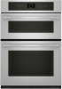
27" (68.6 CM) AND 30" (76.2 CM) ELECTRIC BUILT-IN MICROWAVE/OVEN COMBINATION PRODUCT MODEL SERIES JMW2327W JMW2330W JMW2427W JMW2430W JMW3430W ELECTRICAL CONNECTION If codes permit and a separate ground wire is used, it is recommended that a qualified electrical installer determine that the ground path and the wire gauge are in accordance with local codes. Check with a qualified electrical installer if you are not sure the oven is properly grounded. This oven must be connected to a grounded metal, permanent wiring system. Be sure that the electrical connection and wire size are adequate and in conformance with the National Electrical Code, ANSI/NFPA 70-latest edition or CSA Standards C22.194, Canadian Electrical Code, Part 1 and C22.2 No. O-M91latest edition, and all local codes and ordinances. To properly install your oven, you must determine the type of electrical connection you will be using and follow the instructions provided for it here. q Oven must be connected to the proper electrical voltage and frequency as specified on the model/serial number rating plate. The model/serial number rating plate is located near center vent of the lower oven. See the following illustration. A PRODUCT DIMENSIONS Product Dimensions A B E D C 27" (68.6 cm) models A. 25¹⁄₄" (64.1 cm) max. recessed width B. 43 109.4 cm) max. overall height C. 26³⁄₄" (67.9 cm) max. overall width D. 23⁵⁄₈" (60.0 cm) max. overall depth E. 41" (104.2 cm) max. recessed height Cabinet Dimensions 30" (76.2 cm) models A. 28" (71.1 cm) max. recessed width B. 43 109.4 cm) max. overall height C. 29³⁄₄" (75.6 cm) max. overall width D. 23⁵⁄₈" (60.0 cm) max. overall depth E. 41" (104.2 cm) max. recessed height A A. Model/serial number plate (located on underside of center vent) q Models rated from 7.3 to 9 kW at 240 volts (5.4 to 7.4 kW at 208 volts) require a separate 40-amp circuit. Models rated at 4.8 kW and below at 240 volts (3.6 kW and below at 208 volts) require a separate 20-amp circuit. q A circuit breaker is recommended. q Connect directly to the fused disconnect (or circuit breaker box) through flexible, armored or nonmetallic sheathed, copper cable (with grounding wire). See "Make Electrical Connection" section. q Flexible conduit from the oven should be connected directly to the junction box. q Do not cut the conduit. The length of conduit provided is for serviceability of the oven. q A UL listed or CSA approved conduit connector must be provided. q If the house has aluminum wiring follow the procedure below: 1. Connect a section of solid copper wire to the pigtail leads. 2. Connect the aluminum wiring to the added section of copper wire using special connectors and/or tools designed and UL listed for joining copper to aluminum. Follow the electrical connector manufacturer's recommended procedure. Aluminum/copper connection must conform with local codes and industry accepted wiring practices. Because Whirlpool Corporation policy includes a continuous commitment to improve our products, we reserve the right to change materials and specifications without notice. F E D B G C 27" (68.6 cm) models A. 27" (68.6 cm) min. cabinet width B. 43 110.0 cm) from bottom of cutout to bottom of upper cabinet door C. 19¹⁄₄" (48.9 cm) recommended bottom of cutout to floor. 4" (10.2 cm) to 19¹⁄₄" (48.9 cm) bottom of cutout to floor is acceptable. D. 25¹⁄₂" (64.8 cm) cutout width E. 1¹⁄₂" (3.8 cm) min. bottom of cutout to top of cabinet door F. 41¹⁄₄" (104.8 cm) cutout height G. 24" (61.0 cm) minimum cutout depth 30" (76.2 cm) models A. 30" (76.2 cm) min. cabinet width B. 43 110.0 cm) from bottom of cutout to bottom of upper cabinet door C. 19¹⁄₄" (48.9 cm) recommended bottom of cutout to floor. 4" (10.2 cm) to 19¹⁄₄" (48.9 cm) bottom of cutout to floor is acceptable. D. 28¹⁄₂" (72.4 cm) cutout width E. 1¹⁄₂" (3.8 cm) min. bottom of cutout to top of cabinet door F. 41¹⁄₄" (104.8 cm) cutout height G. 24" (61.0 cm) minimum cutout depth Dimensions are for planning purposes only. For complete details, see Installation Instructions packed with product. Specifications subject to change without notice. Ref. W10221384B 08-18-2009
-
 1
1
 |
 |
