Jensen MS4200RS User Manual - Page 8
Connection overview ISO connector B loudspeakers, Fig. 3, Fig. 4 - 6
 |
View all Jensen MS4200RS manuals
Add to My Manuals
Save this manual to your list of manuals |
Page 8 highlights
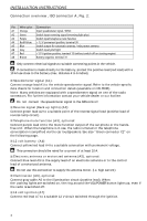
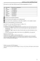
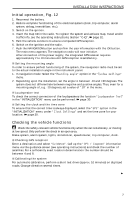
INSTALLATION INSTRUCTIONS Connection overview ISO connector B (loudspeakers), Fig. 3: Pin Wire color B1 Blue B2 Blue/black B3 Grey B4 Grey/black B5 Green B6 Green/black B7 White B8 White/black Connection to loudspeaker + Rear right (RR+) - Rear right (RR-) + Front right (FR+) - Front right (FR-) + Front left (FL+) - Front left (FL-) + Rear left (RL+) - Rear left (RL-) A Use only 4-ohm impedance speakers. A Do not connect either speaker wire to chassis ground. A Use caution when connecting an aftermarket amplifier to the speaker outputs. A Do not connect speakers via an external fader. Connection overview ISO connector C, Fig. 4 - 6 s Yellow connector C1 (Preamp line-out): An amplifier with additional loudspeakers can be connected to the unit via this connector. - Connect the "FRONT" lead to the front left (white) and front right (red) channel of the amplifier. - Connect the "REAR" lead to the rear left (white) and rear right (red) channel of the amplifier. - Connect the blue/yellow lead to the remote control (REMOTE) of the amplifier. s Green connector C2 Telephone input (adapter cable accessories): Connect the loudspeaker output of the mobile phone or hands-free unit to the yellow connector at the end of cable C2. For information about setting the telephone attributes, refer to "INITIALIZATION" ➽ Page 30. s Blue connector C3 (CD changer): You can connect an optional CD changer to the unit. For further information call technical support. 5
-
 1
1 -
2
-
 3
3 -
 4
4 -
 5
5 -
 6
6 -
 7
7 -
 8
8 -
 9
9 -
 10
10 -
 11
11 -
 12
12 -
 13
13 -
14
-
15
-
16
-
17
-
18
-
19
-
20
-
21
-
22
-
23
-
24
-
25
-
26
-
27
-
28
-
29
-
30
-
31
-
32
-
33
-
34
-
35
-
36
-
37
-
38
-
39
-
40
-
41
-
42
-
43
-
44
-
45
-
46
-
47
-
48
-
49
-
50
-
51
-
52
-
53
-
54
-
55
-
56
-
57
-
58
-
59
-
60
-
61
-
62
-
63
-
64
-
65
 |
 |
