Jensen VM8013HD Quick Start Guide - Page 1
Jensen VM8013HD - Screen MultiMedia Receiver Manual
 |
UPC - 043258304315
View all Jensen VM8013HD manuals
Add to My Manuals
Save this manual to your list of manuals |
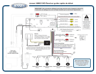
Page 1 highlights
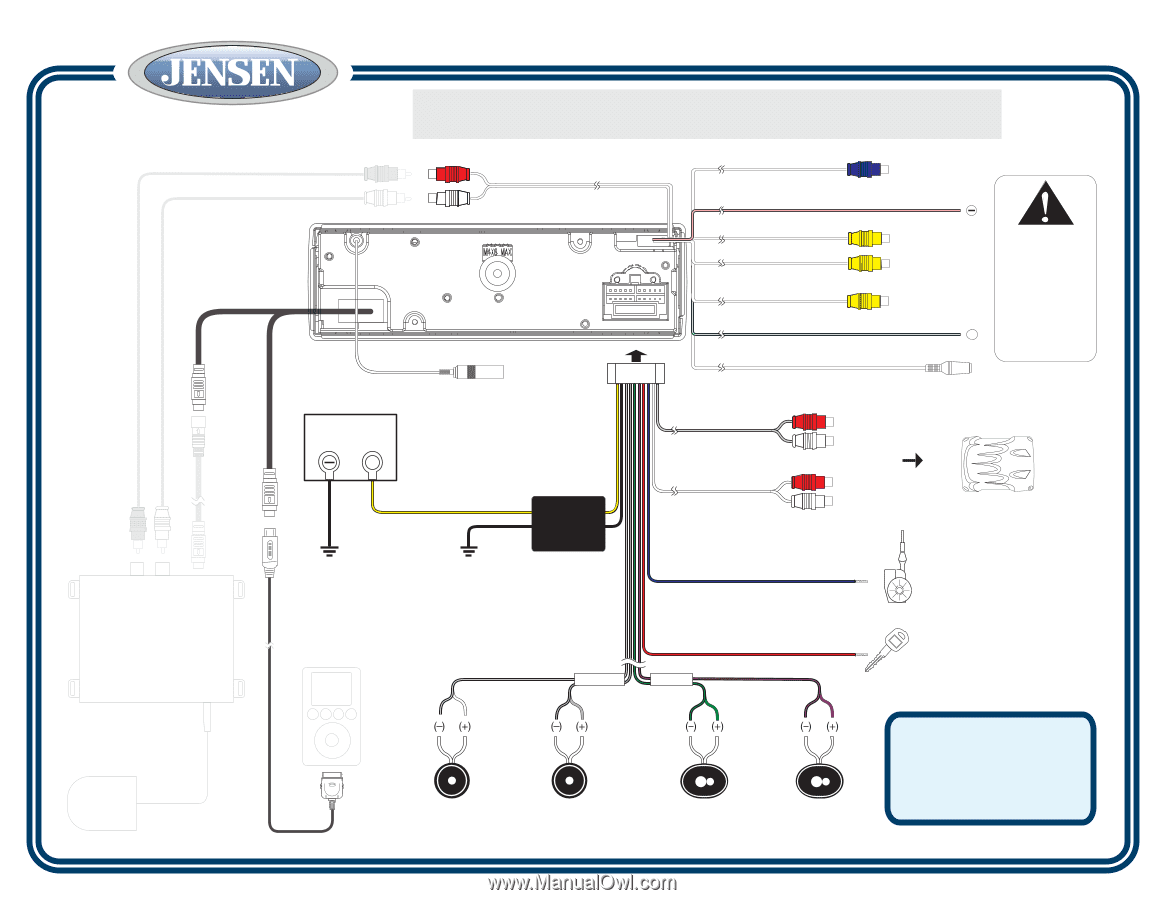
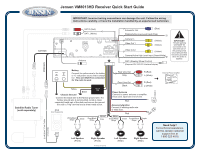
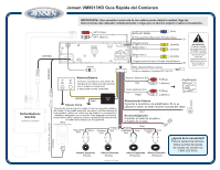
Jensen VM8013HD Receiver Quick Start Guide IMPORTANT: Incorrect wiring connections can damage the unit. Follow the wiring instructions carefully, or have the installation handled by an experienced technician. SAT BUS SAT R (Red) SAT L (White) Antenna Fuse (15A) Subwoofer Out (Blue) Parking/Active Low Level Input (Pink) Camera In Video Out 1 (Yellow) (Yellow) Video Out 2 (Yellow) Camera/Active High Level Input (Green/White) + SWC (Steering Wheel Control) (Requires PAC SWI-PS Interface Adapter) IMPORTANT! The pink parking wire MUST be connected to the switched side of the parking break circuit (the part that becomes grounded when the brake is applied). IPOD BUS () (+) Satellite Radio Tuner (sold separately) jLink/jLink2 iPod Cable (Included) - Battery Connect the yellow wire to the battery or 12 volt power source that is always live. This wire MUST be connected for the radio to work. Yellow Black FILTER BOX Chassis Ground Connect the black wire to the factory ground wire. If a factory ground wire is not provided, locate a clean, unpainted metal part of the dash and secure the ground wire with a "ring" terminal and a sheet metal screw. iPod (Sold Separately) White/Black Stripe White Gray/Black Stripe FRONT Gray Rear Line Out Gray R (Red) L (White) Front Line Out Black R (Red) L (White) Power Antenna Connect to power antenna or amplifier. If not used, tape bare end of wire. Blue Accessory/Ignition Connect to existing radio wire or radio fuse. REAR Green/Black Stripe Red Green Purple/Black Purple Stripe External Power Amplifier Left Speaker (Front) Right Speaker (Front) Left Speaker (Rear) Right Speaker (Rear) Need help? For technical assistance, call the Jensen customer support line at 1-800-323-4815. Printed in China
-
 1
1 -
 2
2 -
 3
3
 |
 |