Kenmore 3103 Installation Instructions - Page 10
Decorative, Check, Operation
 |
View all Kenmore 3103 manuals
Add to My Manuals
Save this manual to your list of manuals |
Page 10 highlights
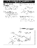
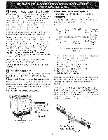
Decorative Rear Trim Installation (if required) 1. Disconnect the power from the range. 2. Make sure the range is leveled. 3. Pull range toward you. 4. Measure the distance between the floor and the surface underneath the cooktop frame. 5. Mark that distance on the wall where the decorative trim will be installed. 6. Draw a line. 7. Place the top of the decorative trim under that line. 8. Using the screws provided fix the decorative trim into the wall. 9. Slide the range back into position as far as it will go and reconnect the power source. Trim Figure 10 Check Operation Refer to the Use and Care Guide packaged with the range for operating instructions and for care and cleaning of your range. Remove all packaging from the oven before testing. 11.1 Install Burner Bases and Burner Caps This range is equipped with sealed burners as shown (see Figure 11). a. Unpack burner bases and burner caps. b. Place burner bases over each gas opening. c. Make sure the burner is properly aligned and leveled. Place burner caps over appropriate burner bases. NOTE: There are no burner adjustments necessary on this range. Electrode Figure 1 1 11.2 Turn on Electrical Power and Open Main Shutoff Gas Valve 11.3 Check the Igniters Operation of electric igniters should be checked after range and supply line connectors have been carefully checked for leaks, and range has been connected to electric power. To check for proper lighting: a. Push in and turn a surface burner knob to the LITE position. You will hear the igniter sparking. b. The surface burner should light when gas is available to the top burner. Each burner should light within four (4) seconds after air has been purged from supply lines. Visually check that burner has lit. c. Once the burner lights, the control knob should be rotated out of the LITE position. There are separate ignition devices for each burner. Try each knob separately until all burner valves have been checked. 11.4 Adjust the "LOW" Setting of Surface Burner Valves (see Figure 12) a. Push in and turn each control to LITE until burner ignites. b. Quickly turn knob to LOWEST POSITION. c. If burner goes out, readjust valve as follows: Reset control to OFF. Remove the surface burner control knob, insert a thin-bladed screw driver into the hollow valve stem and engage the slotted screw inside. Flame size can be increased or decreased with the turn of the screw. Adjust flame until you can quickly turn knob from LITE to LOWEST POSITION without extinguishing the flame. Flame should be as small as possible without going out. Figure 12 10
-
 1
1 -
2
-
3
-
4
-
 5
5 -
 6
6 -
 7
7 -
 8
8 -
 9
9 -
 10
10 -
 11
11 -
 12
12 -
 13
13 -
 14
14 -
 15
15 -
16
-
17
-
18
-
19
-
20
-
21
-
22
-
23
-
24
-
25
-
26
-
27
-
28
 |
 |
