Kenmore 3247 Use and Care Guide - Page 6
Before, Controls, cont'd
 |
View all Kenmore 3247 manuals
Add to My Manuals
Save this manual to your list of manuals |
Page 6 highlights
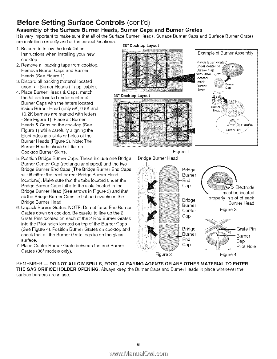
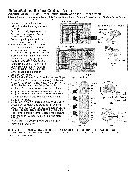
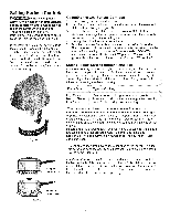
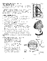
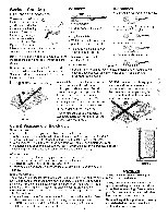
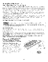
Before Setting Surface Controls (cont'd) Assembly of the Surface Burner Heads, Burner Caps and Burner Grates It is very important to make sure that all of the Surface Burner Heads, Surface Burner Caps and Surface Burner Grates are installed correctly and at the correct locations. 1. Be sure to follow the Installation 30" Cooktop Layout Instructions when installing your new Example of Burner Assembly cooktop. 2. Remove all packing tape from cooktop. Remove Burner Caps and Burner Heads (See Figure 1). 3. Discard all packing material located under all Burner Heads (if applicable). 4. Place Burner Heads & Caps, match the letters located under center of N m 36" Cooktop Layout Match letter located under center of Burner Cap with letter located ,_ BSirdner Head Burner Cap Burner Caps with the letters located inside Burner Head (only 5K, 9.5K and 16.2K burners are marked with letters - See Figure 1). Place all Burner Heads & Caps on the cooktop (See Figure 1) while carefully aligning the Electrodes into slots or holes of the _:_ Electrode Burner Heads (Figure 3). Note: The Burner Heads should sit flat on Cooktop Burner Skirts. 5. Position Bridge Burner Caps. These include one Bridge Burner Center Cap (rectangular shaped) and the two Bridge Burner End Caps (The Bridge Burner End Caps will fit either the front or rear Bridge Burner Head locations). Make sure that the tabs located under the Bridge Burner Caps fall into the slots located in the Bridge Burner Head (See arrows in Figure 2) and that all the Bridge Burner Caps lie flat and evenly on the Bridge Burner Head. 6. Unpack Burner Grates. NOTE: Do not force End Burner Grates down on cooktop. Be careful to line up the 2 Grate Pins located on each of the 2 End Burner Grates Figure 1 Bridge Burner Head I Bridge Burner End Cap Bridge Burner Center Cap _ Electrode must be located properly in slot of each Burner Head Figure 3 into the Pilot holes located on top of the Burner Caps (See Figure 4). Position Burner Grates on cooktop and check that all the Burner Grate legs lie on the glass surface. 7. Place Center Burner Grate between the end Burner Grates (36" models only). _i Figure 2 ...J._/iiiiiiiiiii/ Burner BErinddge Cap _GratePin Burner Cap Pilot Hole Figure 4 REMEMBER -- DO NOT ALLOW SPILLS, FOOD, CLEANING AGENTS OR ANY OTHER MATERIAL TO ENTER THE GAS ORIFICE HOLDER OPENING. Always keep the Burner Caps and Burner Heads in place whenever the surface burners are in use. 6
-
 1
1 -
 2
2 -
 3
3 -
 4
4 -
 5
5 -
 6
6 -
 7
7 -
 8
8 -
 9
9 -
 10
10 -
 11
11 -
 12
12 -
13
-
14
-
15
-
16
 |
 |