Kenmore 4104 Installation Instructions - Page 5
SNPower, Supply, Electrical, Connection, Range - manual
 |
View all Kenmore 4104 manuals
Add to My Manuals
Save this manual to your list of manuals |
Page 5 highlights
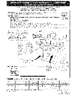
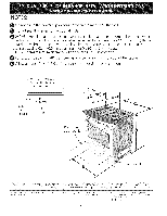
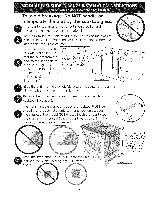
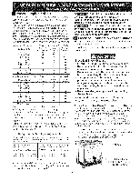
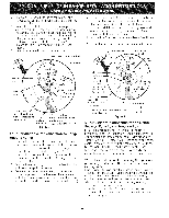
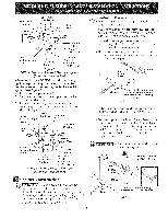
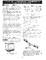
SNPower Supply Cord Kit The user is responsible for connecting the power supply cord to the connection block located behind the back panel access cover. This appliance may be connected by means of permanent "hard wiring" (flexible armored or nonmetallic shielded copper cable), or by means of a power supply cord. Only a power supply cord kit rated at 125/250 volts minimum, 40 amperes minimum and marked for use with ranges shall be used. See chart (below) for cord kit connection opening size rating information. Cord must have either 3 or 4 conductors. Appliance Rating Watts 120V/208V 0-3120 3121-3900 3901-4160 4161-5200 5201-5570 5571-7430 7431-7800 7801-12500 12501-14500 Minimum Conductor Size,AWG CLolnadnudcLt2ors 16 16 14 14 12 12 12 10 8 CoNneduutcratol r 16 16 16 16 16 14 12 12 12 CGonroduunctdor 14 12 12 10 10 10 10 10 10 Appliance Rating Watts Minimum Conductor Size,AWG 120V / 240V 0-3600 3601-4500 4501-4800 4801-6000 6001-6425 6426-8749 8750-14500 14501-16500 16501-24000 L1 and L2 Conductors 16 16 14 14 12 12 10 10 8 Neutral Conductor 16 16 16 16 16 12 12 10 10 Ground Conductor 14 12 12 10 10 10 10 10 8 For mobile homes, new installations, recreational vehicles, or areas where local codes do not permit grounding through neutral, a 4 conductor power supply cord kit rated at 125/250 volts minimum, 40 amperes and marked for use with ranges should be used (see Figure 4). Terminals on end of wires must be either closed loop or open-end spade lugs with upturned ends. Cord must have strain-relief clamp. Range Connection Opening Size Chart Refer to chart below for proper range connection opening size and power supply cord kit ampere rating information. See serial plate on range for kilowatt rating data. See Serial Plate on Range forKW Rating 120/240 Volts 120/208 Volts 0-16.5 Kw 0-12.5 Kw 16.6-22.5 Kw 12.6-18.5 Kw Minimum Cord kit Ampere Rating 40 Amp 50Amp Diameter (inches)of Range Connection Opening Cord Kit DirectConnection 1-3/8 in. 1-3/8in. 1-1/8 in. 1-3/8in. Figure I NOTE: Dual fuel Slide-in Range is shipped from factory with 1 1/8" dia. hole as shown on figure 3. If a larger hole is required, punch out the knockout. Risk of fire or electrical shock exists if the incorrect amperage cord is used, the Installation instructions are not followed, or the strain relief bracket is discarded (see Figure 3). Do not loosen the nuts which secure the factory-installed range wiring to terminal block while connecting range. Electrical failure or loss of electrical connection may occur. Electrical Connection to the Range This appliance is manufactured with the neutral terminal connected to the frame. Note: Refer to the wiring diagram in the center pages of this manual. Electrical Shock Hazard • Electrical ground is required on this appliance. Do not connect to the electrical supply until appliance is permanently grounded. Disconnect power to the circuit breaker or fuse box before making the electrical connection. This appliance must be connected to a grounded, metallic, permanent wiring system, or a grounding connector should be connected to the grounding terminal or wire lead on the appliance. • Do not use the gas supply line for grounding the appliance. Failure to do any of the above could result in a fire, personal injury or electrical shock. Three Conductor Wire Connection to Range (The 3-conductor cord or cable must be replaced with a 4-conductor cord or cable where grounding through the neutral conductor is prohibited in new installations, mobile homes, recreational vehicles or in other areas where local codes do not permit neutral grounding) If local codes permit connection of the frame grounding conductor to the neutral wire of the copper power supply cord (see Figure 3): , Remove the 3 screws at the lower end of the rear wire cover, then bend the lower end of the rear wire cover (access cover) upward to expose range terminal connection block (see Figure 2). Figure 2 BEND REARWIRE COVER HERE FOR ACCESS TO TERMINAL BLOCK
-
 1
1 -
 2
2 -
 3
3 -
 4
4 -
 5
5 -
 6
6 -
 7
7 -
 8
8 -
 9
9 -
 10
10 -
 11
11 -
12
-
13
-
14
-
15
-
16
-
17
-
18
-
19
-
20
-
21
-
22
-
23
-
24
-
25
-
26
-
27
-
28
 |
 |