Kenmore 464722309 Use and Care Guide - Page 20
-24FlangeNut
 |
View all Kenmore 464722309 manuals
Add to My Manuals
Save this manual to your list of manuals |
Page 20 highlights
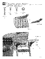
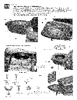
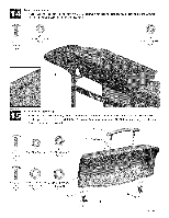
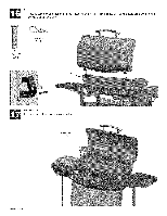
Sideburner Attachsideburnervalvewith #8-32x3/8"machine screws (A). Attachsidebumerpanwith #8x3/8"self-tap screws and 5mm ID 9mm ODfiber washers. Placesideburnerinto shelf(B). Makesurevalve is insidesidebumertube.Attachsideburnerwith wing nut and 5mm ID 9mm ODfiber washer. Insertone end of burnerclip intohole in sidebumertube and hookotherend aroundvalve manifold.Attachsideburnerignitorwire (C). Presssideburnercontrolknobontovalvestem and sideburnergrateontoshelf (D). Attachhingesto back ofshelf with #10-24xl/2"screwsand #10-24nuts (E). SideburnerValve Sideburner Correctly assembled burner-to-valve engagement D SidebumerGrate-/J_@ SideburnerIgnitorWire 6O #8-32x3/8" Screws Qty.2 47 #8x3/8" Self-TapScrews Qty.3 45 SidebumerClip Qty:1 46 WingNut Qty.1 20 • 464810408 27 13 #10-24Xl/2S" crew #10-24FlangeNut Qty.4 Qty.4 ControlKnob X p E
-
 1
1 -
2
-
3
-
4
-
5
-
6
-
7
-
8
-
9
-
10
-
11
-
12
-
13
-
14
-
 15
15 -
 16
16 -
 17
17 -
 18
18 -
 19
19 -
 20
20 -
 21
21 -
 22
22 -
 23
23 -
 24
24 -
 25
25 -
26
-
27
-
28
 |
 |
