Kenmore 60572 Use and Care Guide - Page 2
Check, Dimensions, Disconnect, New Disposer, Mounting, Assembly, Install, Flange, In Sink Hole, - disposal
 |
View all Kenmore 60572 manuals
Add to My Manuals
Save this manual to your list of manuals |
Page 2 highlights
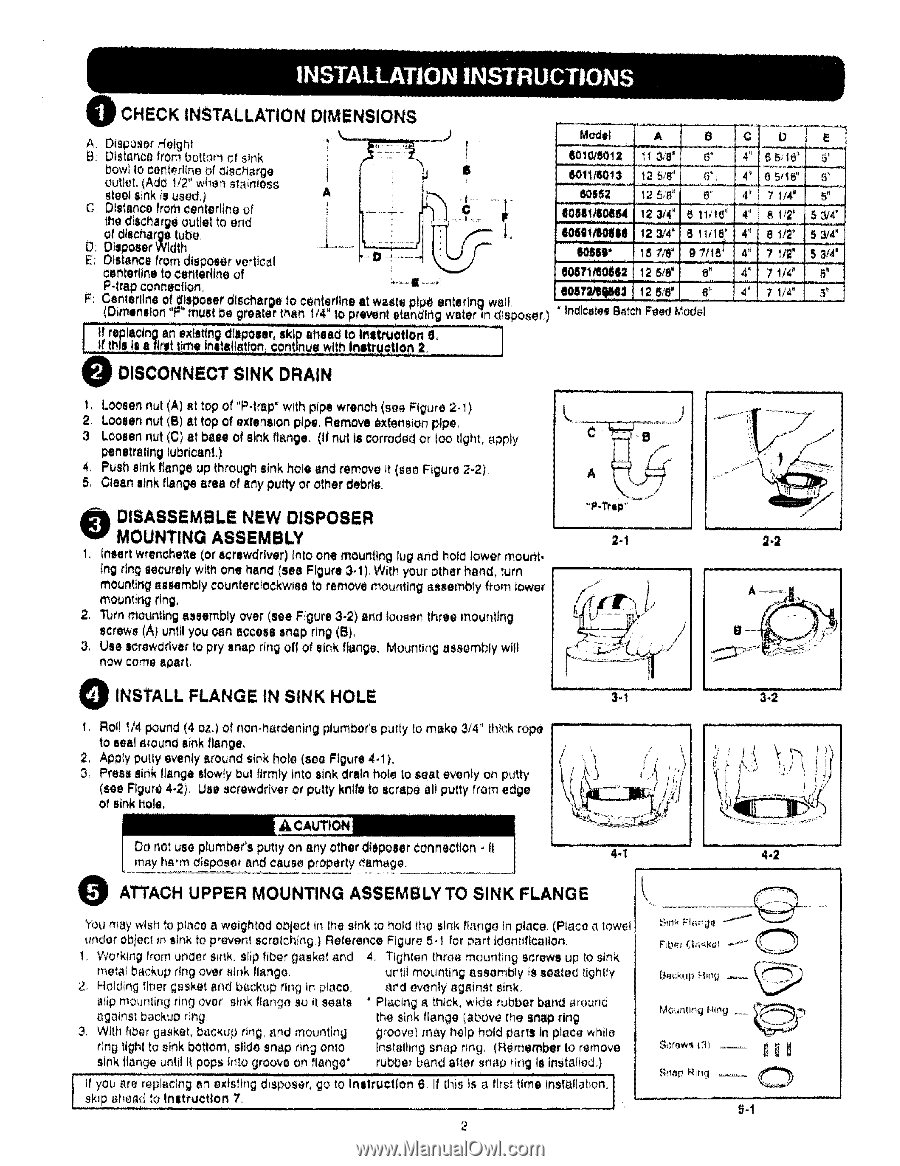
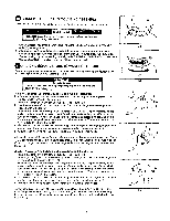
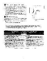
Oi CHECK INSTALLATION DIMENSIONS A: Di,_posorHeight I' B: Distance from bottom at sink bowt to centerline of oiscnargg i gutter. (Ad_ 1/2" wher_stainless steel _lnk is used.] A C: Distance fromeenterltne of the discharge outlet to end of discharge tube, D: Disposer Width E: Distance from disposer vertical contorting to ¢enterttne of P.lrap connection, _---|---.I F: Centerflne of disposer dlsche.rgeto ¢enterllne lit waste p pO enter ng we (Dimension "F" muet be greater ther_t!4" 1oprevent etendlr_g water]n dlsposer,l Model .m_o.= _ _' ie" eol!T=,,!_tlllil3!2 8/8" a" .... ' Indicates B_tchFeedModel _',,,,Z _/f "'_' ...... 4" 7 1/4" 5_ ! I!f_rthgipsleIsclnegflrwant !e_xt_fsetl!nngaild=flJibp(Ofeene=r¢9s_knipt!ra!tuleQwedthtoIrtIsrttlrlutt_U!olollrol n2 8...... '_ DISCONNECT SINK DRAIN t, Looeen nul (A) el top ot "P-trap" with pipe wrench (see Figure 2-1), 2, Loosen nut (B) at top of extension pipe. Remove _xtenSion plp_, 3, Loosen nut (C) at base of eink fie.nee. (if nut Is corroded or Ioo tight, _pply penetrating lubricant,) 4. Push s_nkf_engeup throughsink hole and remove it (_g_ Figure 2-2) 5. Ctean sink flange area of arty putty or ati_er debris, O ISASSEMBLE NEW DISPOSER MOUNTING ASSEMBLY t, [near( wrenohe_e (or ecrewdrlver) into one mounting lug _nd hof_ tower mou_{, {ng rin_ securely with one hand (see Figure 3-1) With your other hand, turn mounting _.embly countercfockwma to remove mounting assembly from tower mounting ring, 2. Turn mounting assembty over (seeFigure 3-2) and loosen three mounttng screws (A) until you oan I_ccess snap ring (B), 3, Use screwdriver to pry sn_p ring off of sink flange. Moui"tlirlg assembly wit( now come apart O INSTALL FLANGE IN SINK HOLE t, Roll I/4 pound (4 oz.) of non-hardening plumber's putty [omake 314" thick rope to ,,eel 8round sink flange, 2, Apply putty evenly around sink hofe (sea Figure 4.1 ). 3, Press sink flange slowty bul firmly into sink drain bole to seat evonty on putty (see Figure 4.2). Use screwdriver or putty knlN to scrape eli putty from edge of sink ftole, ,_ .... 2*1 3-1 __ • _ i 2-2 3-2 Do not use plumber's putty on any other dteposer Connection. It 4-1 4-2 m_y h_rm d_sposer _nd ceu_e property damage, O ATTACH UPPER MOUNTING ASSEMBLY TO SINK FLANGE You may wish to place _ weighted o_lect in the stnk to hol_ (he sink flange in piece. (Place 0, towel under obtect m sink to prever_t scml_hing ) Reference Figure 5-1 for part identtflcallon. 1. Working IrOn under sink, sIip fiber gasket and 4, Tig_',_en three meurtting screw-, up to sir_k metal backup ring over _ink flange, u_{it mounting _9sombly _ssee_ed lightly 2, Holding tiber gasket and b_.ckup rtr_g in piece. _r_ evenly _,g_inet _tnk. _fip mounli_g ring over e!r'_kflange} au il seeI,,i 8galnst i_acku0 ring, 3, With hber gasket, backup rmg, and mounting • Placing _, thick, wide rubber band mound the sink flange (_b'Ove the SnSp ring grOOV_t rrl_y help hold _arts in place while rlng_ighl to sinkbottom, elid_sn_p ringonto tnstalli_g snap rmg, (Remember to remove sink flange un!.il Itpops tr_to groove on flange'. rubber band alter snap ring le installed,) t If you _re repfec, lng 8n extstlng disposer, go to Instruction 6. I! [his is _ f[rs_time tnst_.t 1
1 -
 2
2 -
 3
3 -
 4
4 -
 5
5 -
 6
6 -
 7
7 -
 8
8
 |
 |